 |
 |
 |
| Главная Журналы Популярное Audi - почему их так назвали? Как появилась марка Bmw? Откуда появился Lexus? Достижения и устремления Mercedes-Benz Первые модели Chevrolet Электромобиль Nissan Leaf |
Главная » Журналы » Metal oxide semiconductor 1 ... 30 31 32 33 34 35 36 ... 91 Reference source erdrbrCrc Synchronizing circuit VeVbVc ео.еь ес ± Logic and triggering circuit trigger pulse >Phase,50Hz supply Power circuit Converter group selection and blanking circuit load current Vi signal 3-Phase variable frequency output Load FIGURE 16.29 Block diagram for a circulating current-free cycloconverter control circuit. current-free cycloconverter. The same circuit is also apphcable to a circulating current cycloconverter with the omission of the Converter Group Selection and Blanking Circuit. The Synchronizing circuit produces the modulating voltages {e = -Kvy, Cy = -Kv, e = -KvJ, synchronized with the mains through step-down transformers and proper filter circuits. The Reference Source produces a variable-voltage variable-frequency reference signal (e., e., e.) (three-phase for a three-phase cycloconverter) for comparison with the modulation voltages. Various ways (analog or digital) have been developed to implement this reference source as in the case of the PWM inverter. In one of the early analog schemes (Fig. 16.30) [16] for a three-pulse cycloconverter, a variable-frequency unijunction transistor (UJT) relaxation oscillator of frequency 6/ triggers a ring counter to produce a three-phase square-wave output of frequency f which is used to modulate a single-phase fixed frequency (f) variable amplitude sinusoidal voltage in a three-phase full-wave transistor chopper. The three-phase output contains (f -/j), (f -\- fd) (3/j + f), and so forth, frequency components from where the wanted frequency component (f - fd) is filtered out for each phase using a lowpass filter. For example, with f = 500 Fiz and frequency of the relaxation osciUator varying between 2820 to 3180 Fiz, a three-phase 0-30 Fiz reference output can be obtained with the facUity for phase-sequence reversal. The Logic and Trigger Circuit for each phase involves comparators for comparison of the reference and modulating voltages and inverters acting as buffer stages. The outputs of the comparators are used to clock the flip-flops or latches whose outputs in turn feed the SCR gates through AND gates and pulse amplifying and isolation circuit. The second input to the AND gates is from the Converter Group Selection and Blanking Circuit. In the Converter Group Selection and Blanking Circuit, the zero crossing of the current at the end of each half-cycle is detected and is used to regulate the control signals either to P-group or iV-group converters depending on whether the current goes to zero from negative to positive or positive to Reflecting Oscillator
Fixed frequency sinusoidal oscillot-or negative, respectively. However, in practice, the current that is discontinuous passes through multiple zero crossings while changing direction, which may lead to undesirable switching of the converters. Therefore in addition to the current signal, the reference voltage signal is also used for the group selection and a threshold band is introduced in the current signal detection to avoid inadvertent switching of the converters. Further, a delay circuit provides a blanking period of appropriate duration between the converter group switching to avoid line-to-line short-circuits [16]. In some schemes, the delays are not introduced when a smaU circulating current is aUowed during crossover instants hmited by reactors of limited size and this scheme operates in the so-called dual mode - circulating current as weU as circulating current-free mode for minor and major portions of the output cycle, respectively. A different approach to the converter group selection, based on the closed-loop control of the output voltage where a bias voltage is introduced between the voltage transfer characteristics of the converters to reduce circulating current, is discussed in Reference [12]. Improved Control Schemes, With the development of microprocessors and PC-based systems, digital software control has taken over many tasks in modern cycloconverters, particularly in replacing the low-level reference waveform generation and analog signal comparison units. The reference waveforms can easily be generated in the computer, stored in the EPROMs and accessed under the control of a stored program and microprocessor clock osciUator. The analog signal voltages can be converted to digital signals by using analog-to-digital converters (ADCs). The waveform comparison can then be made with the comparison features of the microprocessor system. The addition of time delays and intergroup blanking can also be achieved with digital techniques and computer software. A modification of the cosine firing control, using communication principles such as regular sampling in preference to the natural sampling (discussed so far) of the reference waveform yielding a stepped sine wave before comparison with the cosine wave [17], has been shown to reduce the presence of subharmonics (to be discussed later) in the circulating current cycloconverter, and to facilitate microprocessor-based implementation, as in the case of the PWM inverter. 16.4.4 Cycloconverter Harmonics and Input Current Waveform The exact waveshape of the output voltage of the cycloconverter depends on: (i) the pulse number of the converter; (ii) the ratio of the output to input frequency (/o J); (iii) the relative level of the output voltage; (iv) load displacement angle; (v) circulating current or circulating current-free operation; and (vi) the method of control of the firing instants. The harmonic spectrum of a cycloconverter output voltage is different and more complex than that of a phase-controlled converter. It has been revealed [12] that because of the continuous to-and-fro phase modulation of the converter firing angles, the harmonic distortion components (known as necessary distortion terms) have frequencies that are sums and differences between multiples of output and input supply frequencies. Circulating Current-Free Operation, A derived general expression for the output voltage of a cycloconverter with circulating current-free operation [12] shows the following spectrum of harmonic frequencies for the 3-pulse, 6-pulse, and 12-pulse cycloconverters employing the cosine modulation technique: 3-pulse: /,н = \3(2k - l)f, ± 2nQ and \6kf, ± (2n + 1)/J 6-pulse:/,h = 6/c/;±(2n+l)/J 12-pulse:/,h = 6/c/;±(2n+l)/J (16.30) where к is any integer from unity to infinity and n is any integer from zero to infinity. It may be observed that for certain ratios of /J, the order of harmonics may be less or equal to the desired output frequency. AU such harmonics are known as subharmonics as they are not higher multiples of the input frequency. These subharmonics may have considerable amplitudes (e.g., with a 50-Hz input frequency and 35-Hz output frequency, a subharmonic of frequency 3 X 50 - 4 X 35 = 10 Hz is produced whose magnitude is 12.5% of the 35-Hz component [17]) and are difficult to filter and thus are objectionable. Their spectrum increases with the increase of the ratio f/f and thus limits its value at which a tolerable waveform can be generated. Circulating-Current Operation, For circulating-current operation with continuous current, the harmonic spectrum in the output vohage is the same as that of the circulating current-free operation except that each harmonic family now terminates at a definite term, rather than having an infinite number of components. They are 3-pulse: /,н = 3(2/c - Щ ± 2n/J, n < 3(2k - 1) + 1 and \6kfi ± (2n + 1)/J, (2n + 1) < (6k + 1) 6-pulse: /,н = \6kf, ± (2n + 1)/J, (2n + 1) < (6k + 1) 12-pulse: /,н = \6kf, ± (2n + 1)/J, (2n + 1) < (I2k + 1) (16.31) The amplitude of each harmonic component is a function of the output voltage ratio for the circulating current cycloconverter and the output voltage ratio as weU as the load displacement angle for the circulating current-free mode. From the point of view of maximum useful attainable output-to-input frequency ratio (fj/fo) with the minimum amplitude of objectionable harmonic components, a guideline is available in Reference [12] for it as 0.33, 0.5, and 0.75 for the 3-, 6-, and 12-pulse cycloconverter, respectively. However, with modification of the cosine wave modulation timings such as regular sampling [17] in the case of circulating current cycloconverters only and using a subharmonic detection and feedback control concept [18] for both circulating- and circulating-current-free cases, the subharmonics can be suppressed and useful frequency range for the naturally commutated cycloconverters can be increased. Other Harmonic Distortion Terms, Besides the harmonics as mentioned, other harmonic distortion terms consisting of frequencies of integral multiples of desired output frequency appear if the transfer characteristic between the output and reference voltages is not linear. These are caUed unnecessary distortion terms, which are absent when the output frequencies are much less than the input frequency. Further, some practical distortion terms may appear due to some practical nonlinea-rities and imperfections in the control circuits of the cycloconverter, particularly at relatively lower levels of output voltage. Input Current Waveform, Although the load current, particularly for higher pulse cycloconverters, can be assumed to be sinusoidal, the input current is more complex as it is made of pulses. Assuming the cycloconverter to be an ideal switching circuit without losses, it can be shown from the instantaneous power balance equation that in a cycloconverter supplying a single-phase load the input current has harmonic components of frequencies (f ± 2/), caUed characteristic harmonic frequencies that are independent of pulse number and they result in an osciUatory power transmittal to the ac supply system. In the case of a cycloconverter feeding a balanced three-phase load, the net instantaneous power is the sum of the three oscillating instantaneous powers when the resultant power is constant and the net harmonic component is greatly reduced compared to that of the single-phase load case. In general, the total rrns value of the input current waveform consists of three components - in-phase, quadrature, and the harmonic. The in-phase component depends on the active power output while the quadrature component depends on the net average of the oscillatory firing angle and is always lagging 16.4.5 Cycloconverter Input Displacement/ Power Factor The input supply performance of a cycloconverter such as displacement factor or fundamental power factor, input power factor and the input current distortion factor are defined similarly to those of the phase-controlled converter. The harmonic factor for the case of a cycloconverter is relatively complex as the harmonic frequencies are not simple multiples of the input frequency but are sums and differences between multiples of output and input frequencies. Irrespective of the nature of the load, leading, lagging or unity power factor, the cycloconverter requires reactive power decided by the average firing angle. At low output vohage, the average phase displacement between the input current and the voltage is large and the cycloconverter has a low input displacement and power factor. Besides the load displacement factor and output voltage ratio, another component of the reactive current arises due to the modulation of the firing angle in the fabrication process of the output voltage [12]. In a phase-controUed converter supplying dc load, the maximum displacement factor is unity for maximum dc output voltage. Fiowever, in the case of the cycloconverter, the maximum input displacement factor is 0.843 with unity power factor load [12, 13]. The displacement factor decreases with reduction in the output voltage ratio. The distortion factor of the input current is given by (Ii/I), which is always less than unity and the resultant power factor (=distortion factor x displace-acement factor) is thus much lower (around 0.76 maximum) than the displacement factor and this is a serious disadvantage of the naturally commutated cycloconverter (NCC). 16.4.6 Effect of Source Impedance The source inductance introduces commutation overlap and affects the external characteristics of a cycloconverter similar to the case of a phase-controlled converter with dc output. It introduces delay in the transfer of current from one SCR to another, and results in a voltage loss at the output and a modified harmonic distortion. At the input, the source impedance causes rounding off of the steep edges of the input current waveforms resulting in reduction in the amplitudes of higher-order harmonic terms as weU as a decrease in the input displacement factor. 16.4.7 Simulation Analysis of Cycloconverter Performance The nonhnearity and discrete time nature of practical cycloconverter systems, particularly for discontinuous current conditions, make an exact analysis quite complex and a valuable design and analytical tool is a digital computer simulation of the system. Two general methods of computer simulation of the cycloconverter waveforms for RL and induction motor loads with circulating current and circulating current-free operation have been suggested in Reference [19] where one of the methods, which is very fast and convenient, is the crossover points method. This method gives the crossover points (intersections of the modulating and reference waveforms) and the conducting phase numbers for both P- and N-converters from which the output waveforms for a particular load can be digitally computed at any interval of time for a practical cycloconverter. 16.4.8 Forced-Commutated Cycloconverter (FCC) The naturaUy commutated cycloconverter (NCC) with SCRs as devices discussed so far, is sometimes referred to as a restricted frequency changer as, in view of the allowance on the output voltage quality ratings, the maximum output voltage frequency is restricted (/ Ji) as mentioned earher. With devices replaced by fully controlled switches such as forced-commutated SCRs, power transistors, IGBTs, GTOs, and so forth, a force-commutated cycloconverter (FCC) can be built where the desired output frequency is given by = \js- JiV when f = switching frequency, which may be larger or smaUer than the f. In the case when > /J, the converter is caUed the Unrestricted Frequency Changer (UFC) and when < f, it is caUed a Slow Switching Frequency Changer (SSFC). The early FCC structures have been treated comprehensively in Reference [ 13]. It has been shown that in contrast to the NCC, when the input displacement factor (IDF) is always lagging, in UFC it is leading when the load displacement factor is lagging and vice versa, and in SSFC, it is identical to that of the load. Further, with proper control in an FCC, the input displace- ment factor can be made unity (UDFFC) with concurrent composite voltage waveform or controUable (CDFFC) where P-converter and iV-converter voltage segments can be shifted relative to the output current wave for control of IDF continuously from lagging via unity to leading. In addition to aUowing bilateral power flow, UFCs offer an unhmited output frequency range, good input voltage utihzation, do not generate input current and output voltage subharmonics, and require only nine bidirectional switches (Fig. 16.31) for a three-phase to three-phase conversion. The main disadvantage of the structures treated in Reference [13] is that they generate large unwanted low-order input current and output voltage harmonics that are difficult to filter out, particularly for low-output voltage conditions. This problem has largely been solved with the introduction of an imaginative PWM voltage-control scheme in Reference [20], which is the basis of newly designated converter caUed the Matrix Converter (also known as PWM Cycloconverter) which operates as a Generalized Solid-State Transformer with significant improvement in voltage and input current waveforms resulting in sine-wave input and sine-wave output as discussed in the next section. Д t4otrtx Converter BidtrectfonolSMtches 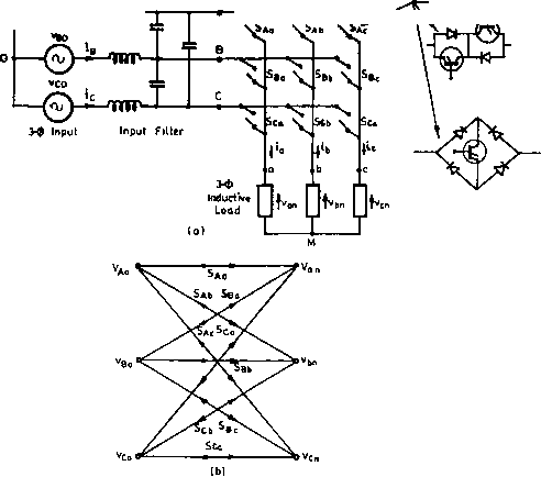 FIGURE 16.31 (a) The converter in (a). matrix converter (force-commutated cycloconverter) circuit with input filter; (b) switching matrix symbol for 16.5 Matrix Converter The matrix converter (MC) is a development of the force-commutated cycloconverter (FCC) based on bidirectional fully controlled switches, incorporating PWM voltage control, as mentioned earher. With the initial progress reported in References [20]-[22], it has received considerable attention as it provides a good alternative to the double-sided PWM voltage-source rectifier-inverters having the advantages of being a single-stage converter with only nine switches for three-phase to three-phase conversion and inherent bidirectional power flow, sinusoidal input/output waveforms with moderate switching frequency, the possibility of compact design due to the absence of dc link reactive components and controUable input power factor independent of the output load current. The main disadvantages of the matrix converters developed so far are the inherent restriction of the voltage transfer ratio (0.866), a more complex control and protection strategy, and above aU the nonavailability of a fully controUed bidirectional high-frequency switch integrated in a sihcon chip (Triac, though bUateral, cannot be fully controUed). The power circuit diagram of the most practical three-phase to three-phase (Зф-Зф) matrix converter is shown in Fig. 16.31a, which uses nine bidirectional switches so arranged that any of three input phases can be connected to any output phase as shown in the switching matrix symbol in Fig. 16.31b. Thus, the voltage at any input terminal may be made to appear at any output terminal or terminals while the current in any phase of the load may be drawn from any phase or phases of the input supply. For the switches, the inverse-paraUel combination of reverse-blocking self-controUed devices such as Power MOSFETs or IGBTs or transistor-embedded diode bridge as shown have been used so far. The circuit is caUed a matrix converter as it provides exactly one switch for each of the possible connections between the input and the output. The switches should be controUed in such a way that, at any time, one and only one of the three switches connected to an output phase must be closed to prevent short-circuiting of the supply lines or interrupting the load-current flow in an inductive load. With these constraints, it can be visualized that from the possible 512 (= 2) states of the converter, only 27 switch combinations are allowed as given in Table 16.1, which includes the resulting output line voltages and input phase currents. These combinations are divided into three groups. Group I consists of six combinations when each output phase is connected to a different input phase. In Group II, there are three subgroups, each having six combinations with two output phases short-circuited (connected to the same input phase). Group III includes three combinations with aU output phases short-circuited. With a given set of input three-phase voltages, any desired set of three-phase output voltages can be synthesized by TABLE 16.1 Three-phase/three-phase matrix converter switching combinati ons
adopting a suitable switching strategy. However, it has been shown [22, 31] that regardless of the switching strategy there are physical limits on the achievable output voltage with these converters as the maximum peak-to-peak output voltage cannot be greater than the minimum voltage difference between two phases of the input. To have complete control of the synthesized output voltage, the envelope of the three-phase reference or target voltages must be fully contained within the continuous envelope of the three-phase input voltages. Initial strategy with the output frequency voltages as references reported the limit as 0.5 of the input as shown in Fig. 16 32a. This can be increased to 0.866 by adding a third harmonic voltage of input frequency (Vj/4) cos3a;t to aU target output voltages and subtracting from them a third harmonic voltage of output frequency (V/6) cos 3a;t as shown in Fig. 16.32b [22, 31]. However, this process involves a considerable amount of additional computations in synthesizing the output voltages. The other alternative is to use the space vector modulation (SVM) strategy as used in PWM inverters without adding third harmonic components but it also yields the maximum voltage transfer ratio as 0.866. An ac input LC filter is used to eliminate the switching ripples generated in the converter and the load is assumed to be sufficiently inductive to maintain continuity of the output currents. connected, the voltages v, v, v at the output terminals are related to the input voltages Уд, V, Vo 16.5.1 Operation and Control Methods of the Matrix Converter The converter in Fig. 16.31 connects any input phase (A, B, and C) to any output phase (a, b, and c) at any instant. When 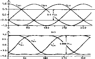 FIGURE 16.32 Output voltage limits for three-phase ac-ac matrix converter: (a) basic converter input voltages; (b) maximum attainable with inclusion of third harmonic voltages of input and output frequency to the target voltages.
Aa Ba Ca Ab Bb cb . Ac Bc Cc Bo LCo (16.32)
where S through Sq are the switching variables of the corresponding switches shown in Fig. 16.31. For a balanced hnear star-connected load at the output terminals, the input phase currents are related to the output phase currents by Aa Ab Ac Ba Bb Bc Ca Cb Cc Note that the matrix of the switching variables in Eq. (16.33) is a transpose of the respective matrix in Eq. (16.32). The matrix converter should be controUed using a specific and appropriately timed sequence of the values of the switching variables, which wiU result in balanced output voltages having the desired frequency and amplitude, while the input currents are balanced and in phase (for unity IDF) or at an arbitrary angle (for controUable IDF) with respect to the input voltages. As the matrix converter, in theory, can operate at any frequency, at the output or input, including zero, it can be employed as a three-phase ac/dc converter, dc/three-phase ac converter, or even a buck/boost dc chopper and thus as a universal power converter. The control methods adopted so far for the matrix converter are quite complex and are subjects of continuing research [22-31]. Of the methods proposed for independent control of the output voltages and input currents, two methods are of wide use and wiU be reviewed briefly here: (i) the Venturini method based on a mathematical approach of transfer function analysis; and (ii) the Space Vector Modulation (SVM) approach (as has been standardized now in the case of PWM control of the dc link inverter). Venturini method. Given a set of three-phase input voltages with constant amplitude V and frequency = ш^/2я, this method calculates a switching function involving the duty cycles of each of the nine bidirectional switches and generates the three-phase output voltages by sequential piecewise-sampling of the input waveforms. These output voltages foUow a predetermined set of reference or target voltage waveforms and with a three-phase load connected, a set of input currents and angular frequency should be in phase for unity IDF or at a specific angle for controUed IDF. A transfer function approach is employed in Reference [29] to achieve the previously mentioned features by relating the input and output voltages and the output and input currents as
ШцСО mi2(0 mi3(t) 2i(0 22(0 2з(0 .3i(0 32(0 33(0. mn(t) m2i(t) m3i(t) 12(0 22(0 32(0 ,1з(0 2з(0 3з(0 .2(0 Mt). (16.34) (16.35) where the elements of the modulation matrix my(t) (i, j = 1, 2, 3) represent the duty cycles of a switch connecting output phase i to input phase j within a sample switching interval. The elements of mij(t) are hmited by the constraints 0<m,j(t)<l and j:m,j(t) = l (i= 1,2,3) The set of three-phase target or reference voltages to achieve the maximum voltage transfer ratio for unity IDF is coscot cos((joj - 120°)
cos(3(jOit) cos(3a;t) cos(3a;t) cos(3a;,t) cos(3a;t) cos(3a;t) (16.36) where V and V are the magnitudes of output and input fundamental voltages of angular frequencies cOq and respectively. With V < 0.866 V-, a general formula for the duty cycles mij(t) is derived in Reference [29]. For unity IDF condition, a simplified formula is 1 +2cos(a;,t-20- 1)60°) cos(a;,t-2(i- 1)60°) -cos(3a;,t) - -cos(3a;t) 2л/3 6 . [cos(4(Dit-2(j- 1)60°) - cos(2a;,t - 2(1 -;)60°] (16.37) where i, j = 1, 2, 3 and q = Vomlim The method developed as in the preceding is based on a Direct Transfer Function (DTF) approach using a single modulation matrix for the matrix converter, employing the switching combinations of all three groups in Table 16.1. Another approach caUed Indirect Transfer Function (ITF) approach [23, 24] considers the matrix converter as a combination of PWM voltage source rectifier-PWM voltage source inverter (VSR-VSI) and employs the already weU-estabhshed VSR and VSI PWM techniques for MC control utilizing the switching combinations of Group II and Group III only of Table 16.1. The drawback of this approach is that the IDF is limited to unity and the method also generates higher and fractional harmonic components in the input and the output waveforms. SVM Method, The space vector modulation is now a weU-documented inverter PWM control technique that yields high voltage gain and less harmonic distortion compared to the other modulation techniques as discussed in Chapter 14, Section 14.6. Fiere, the three-phase input currents and output voltages are represented as space vectors and SVM is apphed simultaneously to the output voltage and input current space vectors. Applications of the SVM algorithm to control of matrix converters have appeared in the literature [27-30] and shown to have inherent capability to achieve full control of the instantaneous output voltage vector and the instantaneous current displacement angle even under supply voltage disturbances. The algorithm is based on the concept that the MC output line voltages for each switching combination can be represented as a voltage space vector defined by Vo=- Kb + bc exp( ;120°) + v exp(-;120°)] (16.38) Of the three groups in Table 16.1, only the switching combinations of Group II and Group III are employed for the SVM method. Group II consists of switching state voltage vectors having constant angular positions and are caUed active or stationary vectors. Each subgroup of Group II determines the position of the resuhing output voltage space vector, and the six state space voltage vectors form a six-sextant hexagon used to synthesize the desired output voltage vector. Group III comprises the zero vectors positioned at the center of the output voltage hexagon and these are suitably combined with the active vectors for the output voltage synthesis. The modulation method involves selection of the vectors and their on-time computation. At each sampling period T, the algorithm selects four active vectors related to any possible combinations of output voltage and input current sectors in addition to the zero vector to construct a desired reference voltage. The amplitude and the phase angle of the reference voltage vector are calculated and the desired phase angle of the input current vector are determined in advance. For computation of the on-time periods of the chosen vectors, these are combined into two sets leading to two new vectors adjacent to the reference voltage vector in the sextant and having the same direction as the reference voltage vector. Applying the standard SVM theory, the general formulas derived for the vector on- times, which satisfy, at the same time, the reference output vohage and input current displacement angle in Reference [29], are to = a/3C0S( a/3C0S( а/З COS ( -sin(6O°-0 )sin(6O°-0,) -sin(60° - 0,)sin0 -sin0 sin(60° -0;) - sin sin 0; (16.39) cos ( where ({ = voltage transfer ratio, is the input displacement angle chosen to achieve the desired input power factor (with ф- = 0, a maximum value of = 0.866 is obtained), 9 and are the phase displacement angles of the output voltage and input current vectors, respectively, whose values are limited within the 0-60° range. The on-time of the zero vector is (16.40) The integral value of the reference vector is calculated over one sample time interval as the sum of the products of the two adjacent vectors and their on-time ratios. The process is repeated at every sample instant. Control Implementation and Comparison of the Two Methods. Both methods need a Digital Signal Processor (DSP)-based system for their implementation. In one scheme [29] for the Venturini method, the programmable timers, as available, are used to time out the PWM gating signals. The processor calculates the six switch duty cycles in each sampling interval, converts them to integer counts, and stores them in the memory for the next sampling period. In the SVM method, an EPROM is used to store the selected sets of active and zero vectors and the DSP calculates the on-times of the vectors. Then with an identical procedure as in the other method, the timers are loaded with the vector on-times to generate PWM waveforms through suitable output ports. The total computation time of the DSP for the SVM method has been found to be much less than that of the Venturini method. Comparison of the two schemes shows that while in the SVM method the switching losses are lower, the Venturini method shows better performance in terms of input current and output voltage harmonics 16.5.2 Commutation and Protection Issues in a Matrix Converter As the matrix converter has no dc link energy storage, any disturbance in the input supply voltage will affect the output voltage immediately and a proper protection mechanism has to be incorporated, particularly against overvoltage from the supply and overcurrent in the load side. As mentioned, two types of bidirectional switch configurations have hitherto been used - one, the transistor (now IGBT) embedded in a diode bridge, and the other, the two IGBTs in antiparaUel with reverse voltage blocking diodes (shown in Fig 16.31). In the latter configuration, each diode and IGBT combination operates in two quadrants only, which eliminates the circulating currents otherwise built up in the diodo-bridge configuration that can be limited by only bulky commutation inductors in the hues. The MC does not contain freewheeling diodes that usually achieve safe commutation in the case of other converters. To maintain the continuity of the output current as each switch turns off, the next switch in sequence must be immediately turned on. In practice, with bidirectional switches, a momentary short-circuit may develop between the input phases when the switches cross over and one solution is to use a semisoft current commutation using a multistepped switching procedure to ensure safe commutation [28, 34]. This method requires independent control of each two-quadrant switches, sensing the direction of the load current and introducing a delay during the change of switching states. A clamp capacitor connected through two three-phase fuU-bridge diode rectifiers involving an additional 12 diodes (a new configuration with the number of additional diodes reduced to six using the antiparallel switch diodes has been reported [34]) at the input and output hues of the MC serves as a voltage clamp for possible voltage spikes under normal and fault conditions. A three-phase single-stage LC filter consisting of three capacitors in star and three inductors in the line is used to adequately attenuate the higher-order harmonics and render sinusoidal input current. Typical values of L and С based on a 415-V converter with a maximum line current of 6.5 A and a lillliT; 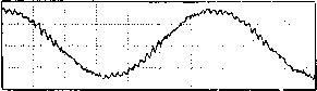 FIGURE 16.33 Experimental waveforms for a matrix converter at 30-Hz frequency from a 50-Hz input: (a) output line voltage; and (b) output line current. switching frequency of 20 kHz are 3 mH and 1.5 only [32]. The filter may cause a minor phase shift in the input displacement angle that needs correction. Figure 16.33 shows typical experimental waveforms of output line voltage and line current of an MC. The output line current is mostly sinusoidal except for a smaU ripple, when the switching frequency is around 1 kHz only. 16.6 Applications of AC/AC Converters 16.6.1 Applications of AC Voltage Controllers AC voltage controllers are used either for control of the rms value of voltage or current in lighting control, domestic and industrial heating, speed control of fan, pump or hoist drives, soft starting of induction motors, so forth, or as static ac switches (on/off control) in transformer tap changing, temperature control, speed stabilization of high inertia induction motor drives such as centrifuge, capacitor switching in static reactive power compensation, and so forth. In fan or pump drives with induction motors, the torque varies as the square of the speed. Thus the speed control is required in a narrow range and an ac voltage controUer is suitable for an induction motor with a fuU load slip of 0.1 to 0.2 in such applications. For these drives, braking or reverse operations are not needed, but for the crane hoist drive, both motoring and braking are needed and a four-quadrant ac voltage controller can be obtained by a modification of the ac voltage controUer circuit as shown in Fig. 16.34. The SCR pairs A, B, and С provide operation in quadrants I and IV and B, and С in quadrants II and III. WhUe changing from one set of SCR pairs to another, care should be taken to ensure that the incoming pair is activated only after the outgoing pair is fully turned off. в 7 С  с The ac voltage controUers are being used increasingly for soft-starting of induction motors, as they have a number of advantages over the conventional starters, such as smooth acceleration and deceleration, ease in implementation of current control, simple protection against single-phasing or unbalanced operation, reduced maintenance and losses, absence of current inrush, and so forth. Even for the fixed-speed industrial applications, the voltage controUers can be used to provide a reduced stator voltage to an induction motor to improve its efficiency at hght load and result in energy saving. Operation at an optimum voltage reduces the motor flux, which, in turn, reduces the core loss and the magnetizing component of the stator copper loss. Considerable savings in energy can be obtained in applications where a motor operates at no load for a significant time, such as in driUs, machine tools, woodworking machines, reciprocating air-compressors, and so forth. A popular approach to find an optimum operating voltage is to maximize the motor power factor by maintaining a minimum phase shift between the voltage and current after sensing them. The ac switch with on/off control used in driving a high-inertia centrifuge involves switching on of the motor when the speed of the centrifuge drops below the minimum aUowable level and switching off motor when the speed reaches the maximum aUowable level - thus maintaining a constant average speed. An identical scheme of control is used with an ac switch for temperature control of an electric heater or air-conditioner. Integral-cycle control is weU suited to heating control whUe it may cause flicker in normal incandescent lighting control and speed fluctuations in motor control. However, with this control less voltage distortion is produced in the ac supply system and less radio frequency interference is propagated when compared with the phase-controUed system. 16.6.2 Applications of Cycloconverters Cycloconverters as frequency changers essentially find weU-established applications in: (i) high-power low-speed reversible ac motor drives with constant frequency input; and (ii) constant frequency power supplies with a variable frequency input as in the VSCF (variable-speed constant frequency) system. They also find potential applications in: (iii) controllable VAR generators for power factor correction; and (iv) ac system interties linking two independent power systems as demonstrated in Reference [13]. Variable Speed AC Drives, In this category, the applications of cycloconverter-controlled induction motor and synchronous motor drives have been adequately reviewed in Reference [15]. Cycloconverter-fed synchronous motors are weU suited for low-speed drives with high torque at standstiU, and high-capacity gearless cement mills (tube or baU-miU above 5 MW) have been the first applications of these drives. Since the 1960s, as developed by Siemens and Brown Boveri, one of the early instaUations has employed a motor rating of 6.4 MW having a rotor diameter of 5 m and 16.5 m in length while the stator construction is similar to that of a hydroelectric generator with 44 poles requiring 5.5 Hz for a maximum speed of 15rpm. The motor is flanged with the miU cyhnder without additional bearings or wrapped directly around it. This is known as ring motor [35]. With the evolution of field orientation or vector control, cycloconverter-fed synchronous motors have replaced or are replacing the dc drives in the reversing rolhng miUs (2/4 MW) with extreme high dynamic requirements for torque and speed control [36, 48, 49] in mine winders and haulage [37, 49] of similar high ratings, and in icebreakers and ships equipped with diesel generators with power ratings of about 20 MW per unit [38]. In these applications, the cycloconverter-fed synchronous motor is in the self-controiled mode and is known as an ac commutatorless motor when the cycloconverter firing signals are derived from a rotor shaft position sensor so that the frequency is slaved to the rotor speed and not vice versa. As a result the hunting and stability problems are eliminated and the torque is not limited to puU-out value. Further, with field control the motor can be operated at leading power factor when the cycloconverter can operate with load commutation from the motor side at high speed in addition to the line commutation from the supply at low speed, thus providing speed control over a wide range. A cycloconverter-fed ac commutatorless motor was reported in Reference [39] where the cycloconverter is operated both in the sinusoidal and trapezoidal mode - the latter is attractive for a better system power factor and higher voltage output at the cost of increased harmonic content [1]. A stator-flux oriented vector control scheme for 6-pulse circulating current-free cycloconverter-fed synchronous motor with a flux observer suitable for a rolhng mill drive (300-0-300 rpm) is reported in Reference [40]. A 12-pulse, 9.64 MVA, 120/33.1-Hz cycloconverter-linear synchronous motor combination for the Maglev Vehicle ML-500, a high-speed train (517km/hr) has been in the process of development in Japan since the early 1980s [41]. Regarding cycloconverter-fed induction motors, early apphcations were for control of multiple ran-out table motors of a hot strip mill, high-performance servodrives, and controlled slip-frequency drive for diesel electric locomotives. Slip power-controlled drives in the form of static Scherbius drives with very high ratings using a cycloconverter in the rotor of a doubly fed slip-ring induction motor have been in operation for high-capacity pumps, compressors [42], and even in a proton-synchrotron accelerator drive in CERN, Geneva [43]. Although synchronous motors have been preferred for very high-capacity low-speed drives because of their high rating, the ability to control power factor and precisely set speed independent of supply voltage and load variations., induction motors because of their absence of excitation control loop, simple structure, easy maintainability and quick response have been instaUed for cycloconverter-fed drives in Japan. For example, a seamless tube piercing miU [44] where a squirrel-cage 6-pole 3-MW, 188/300-rpm, 9.6/15.38-Hz, 2700-V motor is controlled by a cycloconverter bank of capacity 3750 kVA and output voltage 3190 V. Constant Frequency Power Supplies, Some applications such as aircraft and naval ships need a weU-regulated constant frequency power output from a variable frequency ac power source. For example, in aircraft power conversion, the alternator connected to the engine operating at a variable speed of 10,000 to 20,000 rpm provides a variable frequency output power over a 1200-2400-Hz range, which can be converted to an accurately regulated fixed-frequency output power at 400 Hz through a cycloconverter with a suitable filter placed within a closed loop. The output voltages of the cycloconverter are proportional to the fixed-frequency (400 Hz) sine wave reference voltage generator in the loop. Both synchronous and induction motors can be used for VSCF generation. The static Scherbius system can be modified (known as Kramer drive) by feeding slip power through a cycloconverter to a shaft-mounted synchronous machine with a separate exciter for VSCF generation. A new apphcation in very high-power ratings of constant frequency variable-speed motor generators with a cycloconverter is in pumped storage schemes using reversible pump turbines for adaptation of the generated power to varying loads or keeping the ac system frequency constant. In 1993, a 400-MW variable-speed pumped storage system was commissioned by Hitachi at Qkhawachi Hydropower plant [45] in Japan where the field windings of a 20-pole generator/motor are excited with three-phase low-frequency ac current via slip-rings by a 72-MVA, three-phase 12-pulse line-commuted cycloconverter. The armature terminals rated at 18kV are connected to a 500-kV utility grid through a step-up transformer. The output frequency of the circulating current-free cycloconverter is controlled within ±5 Hz and the line frequency is 60 Hz. The variable-speed system has a synchronous speed of 360 rpm with a speed range -330 to 390 rpm. The operational system efficiency in the pump mode is improved by 3% when compared to the earlier constant speed system. Static VAR Generation, Cycloconverters with a high-frequency (HF) base, either a HF generator or an osciUating LC tank can be used for reactive power generation and control, replacing synchronous condensers or switched capacitors as demonstrated in Reference [13]. If the cycloconverter is controlled to generate output voltage waves whose wanted components are in phase with the corresponding system voltages, reactive power can be supphed in either direction to the ac system by amplitude control of the cycloconverter output voltages. The cycloconverter wiU draw leading current from (that is, it wiU supply lagging current to) the ac system when its output voltage is greater than that of the system voltage and vice versa. 1 ... 30 31 32 33 34 35 36 ... 91 |
|
© 2026 AutoElektrix.ru
Частичное копирование материалов разрешено при условии активной ссылки |