 |
 |
 |
| Главная Журналы Популярное Audi - почему их так назвали? Как появилась марка Bmw? Откуда появился Lexus? Достижения и устремления Mercedes-Benz Первые модели Chevrolet Электромобиль Nissan Leaf |
Главная » Журналы » Metal oxide semiconductor 1 ... 31 32 33 34 35 36 37 ... 91 Interties Between AC Power Systems, The naturaUy commutated cycloconverter (NCC) was originally developed for this apphcation to link a three-phase 50-Hz ac system with a single-phase 16 Hz railway supply system in Germany in the 1930s. Applications involve slip-power-controUed motors with sub- and super-synchronous speeds. The stator of the motor is connected to 50-Hz supply, which is connected to the rotor as weU through a cvcloconverter and the motor drives a single-phase synchronous generator feeding to 16Hz system [46, 47]. A static asynchronous intertie between two different systems of different frequency can be obtained by using two NCCs in tandem, each with its input terminals connected to a common HF base. As long as the base frequency is appropriately higher than that of either system, two system frequencies can either be the same or different. The power factor at either side can be maintained at any desired level [13]. 16.6.3 Applications of Matrix Converters The practical apphcations of the matrix converters, as of now, is very limited. The main reasons are: (i) nonavailabUity of the bUateral fully controlled monolithic switches capable of high-frequency operation; (ii) complex control law implementation; (iii) an intrinsic limitation of the output/input voltage ratio; and (iv) commutation [50] and protection of the switches. To date, the switches are assembled from existing discrete devices resulting in increased cost and complexity and only experimental circuits of capacity weU below 100 kVA have been built . However, with the advances in device technology, it is hoped that the problems wiU be solved eventually and the MC wiU not only replace the NCCs in aU the applications mentioned under Section 16.6.2 but wiU also take over from the PWM rectifier inverters as weU. In Reference [51], it has been shown that with space vector PWM control using overmodulation, the voltage transfer ratio may be increased to 1.05 at the expense of more harmonics and large filter capacitors. References 1. C. Rombaut, G. Seguier, and R. Bausiere, Power Electronic Converters-AC/AC Conversion, McGraw-Hill, New York, 1987. 2. W. Shepherd, Thyristor Control of AC Circuits, Granada Publishing, Great Britain, 1975. 3. M. Rashid, Power Electronics: Circuits, Devices and Applications, Prentice-Hall, Englewood Cliffs, 1993. 4. A. M. Trzynadlowski, Introduction to Modern Power Electronics, John Wiley, New York, 1998. 5. S. B. Dewan and A. Straughen, Power Semiconductor Circuits, John Wiley, New York, 1975. 6. C. W. Lander, Power Electronics, McGraw-Hill, London, 1993. 7. D. W. Hart, Introduction to Power Electronics, Prentice-Hall, Englewood Cliffs, 1997. 8. B. W. Williams, Power Electronics: Devices, Drivers and Applicatioins, Macmillan, London, 1987. 9. G. K. Dubey, S. R. Doradla, A. Joshi, and R. M. K. Sinha, Thyristorised Power Controllers, Wiley Eastern, New Delhi, 1986. 10. S. A. Hamed and B. J. Chalmers, New method of analysis and performance prediction for thyristor voltage controlled RL loads. lEE Proc. В 134: 339-347, Nov 1987. 11. A. K. Chattopadhyay, S. P. Das, and S. Karchowdhury, Computer simulation of three-phase thyristor regulator-fed static and induction motor loads - A generalized approach. Electric Machines and Power Systems 21: 329-342, 1993. 12. B. R. Pelly, Thyristor Phase-Controlled Converters and Cycloconverters, John Wiley, New York, 1971. 13. L. Gyugi and B. R. Pelly, Static Power Frequency Changers: Theory, Design and Applications, Wiley-Interscience, New York, 1976. 14. W. McMurray, The Theory and Design of Cycloconverters, MIT Press. Cambridge, 1972. 15. A. K. Chattopadhyay, Cycloconverters and cycloconverter-fed drives -A Review. /. Indian Inst Sci. 77: 397-419, Sept./Oct 1997. 16. A. K. Chattopadhay and T. J. Rao, Simplified control electronics for a practical cycloconverter. Int /. Electronics 43: 137-150, 1977. 17. B. M. Bird and J. S. Ford, Improvements in phase-controlled circulating current cycloconverters using communication principles. Proc. lEE 121:10, 1146-1149, 1974. 18. P. Syam, P. K. Nandi, and A. K. Chattopadhyay, An improvement feedback technique to suppress sub-harmonics in a naturally commutated cycloconverter. IEEE Trans. Ind. Electron. 45:6, 950-952, Dec. 1998. 19. A. K. Chattopadhyay and T. J. Rao, Methods of digital computation of phase controlled cycloconverter performance, in Conf. Rec. lEEE-lAS Ann. Meet 1978, pp. 432-439. 20. M. Venturini, A new sine-wave in sine-wave out converter technique eliminates reactor elements. Proc. POWERCONSQ 1980, vol. E3-1, pp. E3-1-E3-15. 21. A. Alesina and M. Venturini, The generalised transformer: A new bidirectional waveform frequency converter with continuously adjustable input power factor, in Proc. IEEE-PESC80, pp. 242-252. 22. A. Alesina and M. Venturini, Analysis and design of optimum amplitude nine-switch direct ac-ac converters. IEEE Trans. Power Electron. 4:(1), 101-112, Jan. 1989. 23. P. D. Ziogas, S. I. Khan, and M. Rashid, Some improved forced commutated cycloconverter structures. IEEE Trans. Ind. Appl. Ia-21: 1242-1253, July/August 1985. 24. P. D. Ziogas, S. I. Khan, and M. Rashid, Analysis and design of forced commutated cycloconverter structures and improved transfer characteristics. IEEE Trans. Ind. Electron. IE-33:3, 271-280, Aug. 1986. 25. C. L. Neft and C. D. Shauder, Theory and design of a 30 HP matrix converter, in Conf Rec. lEEE-IAS Ann. Meet 1988, pp. 248-253. 26. A. Ishiguru, T. Furuhashi, and S. Okuma, A novel control method of forced commutated cycloconverters using instantaneous values of input line voltages. IEEE Trans. Ind. Electron. 38:3, 166-172, June 1991. 27. L. Huber, D. Borojevic, and N. Burany, Analysis, design and implementation of the space-vector modulator for forced commutated cycloconverters. lEE Proc. В 139:2, 103-113, Mar. 1992. 28. L. Huber and D. Borojevic, Space vector modulated three-phase to three-phase matrix converter with input power factor correction. IEEE Trans. Ind. Appl. 31: 1234-1246, Nov/Dec. 1995. 29. L. Zhang, C. Watthanasarn, and W. Shepherd, Analysis and comparison of control strategies for ac-ac matrix converters. lEE Proc. Power Elec. Appl. 145:4, 284-294, July 1998. 30. D. Casadei, G. Serra, and A. Tani, Reduction of the input current harmonic content in matrix converters under input/output unbalance. IEEE Trans. Ind. Appl. 145:3, 401-411, June 1998. 31. D. G. Holmes and T. A. Lipo, Implementation of a controlled rectifier using ac-ac matrix converter theory. IEEE Trans. Power Electronics, 7:1, 240-250, Jan. 1992. 32. R Wheeler and D. Grant, Optimised input filter design and low-loss switching techniques for a practical matrix converter. lEE Proc. Elec. Power Appl. 144:1, 53-59, Jan. 1997. 33. B. H. Kwon, B. D. Min, and J. H. Kim, Novel commutation techniques of ac-ac converters. lEE Proc. Elec. Power Appl. 145: 295-300, July 1998. 34. R Nielson, R Blabjerg, and J. K. Pederson, New protection issues of a matrix converter: design considerations for adjustable-speed Dives. IEEE Trans. Ind. Appl. 35:5, 1150-1161, Sept./Oct. 1999. 35. E. Blauenstein, The first gearless drive for a tube mill. Brown Boveri Review 57: 96-105, 1970. 36. W. Timpe, Cycloconverter for rolling mill drives. IEEE Trans. Ind. Appl. IA-18:4, 401-404, 1982. 37. V. K. Madisetti and M. A. Ramlu, Trends in electronic control of mine hoists. IEEE Trans. Ind. Appl. IA-22:6, 1105-1112, 1986. 38. A. W. Hill, R. A. Turton, R. L. Dunzan, and С L. Schwaln, A vector controlled cycloconverter drive for an ice-breaker. IEEE Trans. Ind. Appl. IA-23: 1036-1041, Nov./Dec. 1987. 39. S. P. Das and A. K. Chattopadhyay, Comparison of simulation and test results for an ac commutatorless motor drive, lEE Conf. Proc. PEVD96, 1996, pp. 294-299. 40. S. P. Das and A. K. Chattopadhyay, Observer based stator flux oriented vector control of cycloconverter-fed synchronous motor drive. IEEE Trans. Ind. Appl. IA-33:4, 943-955, July/Aug. 1997. 41. T. Saijo, S. Koike, and S. Takaduma, Characteristics of linear synchronous motor drive cycloconverter for Maglev Vehicle ML-500 at Miyazaki test track. IEEE Trans. Ind. Appl. IA-17: 533-543, 1981. 42. H. W. Weiss, Adjustable speed ac drive systems for pump and compressor applications. IEEE Trans. Ind. Appl. IA-10:1, 162-167, 1975. 43. R. Dirr et al, New electronic control equipment for doubly-fed induction motors of high rating. Siemens Review 3: 121-126, 1972. 44. K. Sugi, Y. Natio, P. Kurosawa, Y. Kano, S. Katayama, and T.Yashida, A microcomputer based high capacity cycloconverter drive for main rolling mill. Proc. IPEQ Tokyo, 1983, pp. 744-755. 45. S. Mori, E. Kita, H. Kojima, T. Sanematsu, A. Shiboya, and A. Bando, Commissioning of 400 MW adjustable speed pumped storage system at okhawachi hydropower plant, in Proc. 1995 CIGRE Symp. 1995, no. 520-04. 46. H. Stemmler, High power industrial drives. Proc. IEEE 82:8, 1266-1286, August 1994. 47. H. Stemmler, Active and reactive load control for converters interconnecting 50 and 16 2/3 Hz, using a static frequency changer cascade. Brown Boveri Review 65:9, 614-618, 1978. 48. R. P. Pallman, First use of cycloconverter-fed ac motors in an aluminium hot strip mill. Siemens Engineering & Automation XIV:2, 26-29, 1992. 49. E. A. Lewis, Cycloconverter drive systems, lEE Conf Proc. PEVD96 1996, pp. 382-389. 50. M. J. Case, The commutation process in the matrix converter, Conf. Proc. EPE-PEMC 2000, Kosice, 2, pp. 109-112. 51. J. Mahlein, O. Simon, and M. Braun, A matrix converter with space vector control enabling overmodulation, Conf Proc. EPE99, Lussanne, Sept. 1999, pp. 1-11. DC/DC Conversion Technique and Nine Series LUO-Converters Fang Lin Luo, Ph.D. Hong Ye, Ph.D. School of Electrical and Electronic Engineering, Block S2, Nanyang Technological University, Nanyang Avenue Singapore 639798 Muhammad H. Rashid, Ph.D. Electrical and Computer Engineering, University of West Florida, 11000 University Parkway, Pensacola, Florida 32514-5754 USA 17.1 17.2 17.3 17.4 17.5 17.6 17.7 17.8 17.9 17.10 17.11 17.12 Introduction...................................................................................... 335 Positive Output Luo-Converters............................................................ 337 17.2.1 Fundamental Topologies 17.2.2 Developed Topologies 17.2.3 Transformer-Type Topologies 17.2.4 Seven (7) Self-Lift DC/DC Converters 17.2.5 Positive Output Luo-Converters 17.2.6 Simplified Positive Output Luo-Converters Negative Output Luo-Converters.......................................................... 353 Double Output Luo-Converters............................................................ 359 17.4.1 Double Output Luo-Converters 17.4.2 Simplified Double Output Luo-Converters Multiple-Quadrant Operating Luo-Converters........................................ 372 17.5.1 Two-Quadrant dc/dc Luo-Converter in Forward Operation 17.5.2 Two-Quadrant dc/dc Luo-Converter in Reverse Operation 17.5.3 Four-Quadrant dc/dc Luo-Converter Switched Capacitor Multiquadrant Luo-Converters.................................. 377 17.6.1 Two-Quadrant Switched-Capacitor dc/dc Luo-Converter 17.6.2 Four-Quadrant Switched-Capacitor dc/dc Luo-Converter Switched Inductor Multiquadrant Luo-Converters................................... 386 17.7.1 Two-Quadrant Switched-lnductor dc/dc Luo-Converter in Forward Operation 17.7.2 Two-Quadrant Switched-lnductor dc/dc Luo-Converter in Reverse Operation 17.7.3 Four-Quadrant Switched-lnductor dc/dc Luo-Converter Multiquadrant ZCS Quasi-Resonant Luo-Converters................................ 390 17.8.1 Two-Quadrant ZCS Quasi-Resonant Luo-Converter in Forward Operation 17.8.2 Two-Quadrant ZCS Quasi-Resonant Luo-Converter in Reverse Operation 17.8.3 Four-Quadrant ZCS Quasi-Resonant Luo-Converter Multiquadrant ZVS Quasi-Resonant Luo-Converters................................ 394 17.9.1 Two-Quadrant ZVS-Quasi-Resonant dc/dc Luo-Converter in Forward Operation 17.9.2 Two-Quadrant ZVS Quasi-Resonant dc/dc Luo-Converter in Reverse Operation 17.9.3 Four-Quadrant ZVS Quasi-Resonant dc/dc Luo-Converter Synchronous Rectifier DC/DC Luo-Converters....................................... 397 17.10.1. Flat Transformer Synchronous Rectifier dc/dc Luo-Converter 17.10.2 Double Current Synchronous Rectifier dc/dc Luo-Converter with Active Clamp Circuit 17.10.3 Zero-Current-Switching Synchronous Rectifier dc/dc Luo-Converter 17.10.4 Zero-Voltage-Switching Synchronous Rectifier dc/dc Luo-Converter Gate Control, Luo-Resonator............................................................... 401 Applications...................................................................................... 402 17.12.1 Thousand-Voh Insulation Test Bench 17.12.2 MIT 42/14-V 3-kW DC/DC Converter 17.12.3 IBM 1.8-V/200-A Power Supply References......................................................................................... 404 17.1 Introduction The dc/dc converters are widely used in industrial applications and computer hardware circuits, and the dc/dc conversion technique has been developed very quickly. Since the 1950s there have been five generations of dc/dc converters developed. They are the first-generation (classical) converters, second-generation (multiquadrant) converters, third-generation (switched-component) converters, fourth-generation (soft-switching) converters, and fifth-generation (synchronous rectifier) converters. The first-generation converters perform in a single-quadrant mode and in a low-power range (up to 100 W). These converters include the buck converter, the boost converter, and the buck-boost converter. However, because of the effects of parasitic elements, the output voltage and power transfer efficiency of aU these converters are restricted. The voltage-hft technique is a popular method that is widely apphed in electronic circuit design because it effectively overcomes the effects of parasitic elements and greatly increases the output voltage. Therefore, these dc/dc converters can convert the source voltage into a higher output voltage with high-power efficiency, high-power density and a simple structure. The second-generation converters perform in two- or four-quadrant operation with medium output power range (say, hundreds of watts or higher). Because of high-power conversion, these converters are usually applied in industrial applications with high-power transmission, for example, dc motor drives with multiquadrant operation. Most of second-generation converters are stiU made of capacitors and inductors, as a result they are large. The third-generation converters are caUed switched-compo-nent dc/dc converters, and are made of either inductors or capacitors, which are called switched inductors and switched capacitors. They usually perform in two- or four-quadrant operation with a high-output power range (say, thousands of watts). As they are made only of inductors or capacitors, they are smaU. Switched-capacitor dc/dc converters are made only of switched-capacitors. Because switched capacitors can be integrated into power semiconductor integrated circuit (1С) chips, they have limited size and work at high switching frequency. They have been successfully employed in the inductorless dc/dc converters and have opened the way to constructing converters with high power density. Therefore, they have drawn much attention from research workers and manufacturers. However, while most of these converters reported in the literature perform single-quadrant operation, some of them work in the push-pull state. In addition, their control circuit and topologies are very complex, especially for the large difference between input and output voltages. Switched-inductor dc/dc converters are made of only inductor, and have been derived from four-quadrant choppers. They usually perform multiquadrant operation with very simple structure. The significant advantage of these converters is their simphcity and high power density. No matter how large the difference between the input and output voltages, only one inductor is required for each switched inductor dc/dc converter. Therefore, they are in great demand for industrial apphcations. The fourth-generation converters are called soft-switching converters. The soft-switching technique involves many methods implementing resonance characteristics, and one popular method is the resonant-switching method. The two main groups are zero-current-switching (ZCS) and zero-voltage- switching (ZVS), and as reported in the literature, they usually perform in single-quadrant operation. We have developed this technique in the two- and four-quadrant operation for the high-output power range (say, thousands of watts). Multiquadrant ZCS/ZVS quasi-resonant converters (QRC) implement the ZCS/ZVS technique in four-quadrant operation. As switches turn-on and turn-off the moment the current/voltage is equal to zero, the power losses during switching on and off become zero. Consequently, these converters have high power density and transfer efficiency. Usually, the repeating frequency is not very high and the converters work in a monoresonance frequency, and the components of higher-order harmonics are very low. Using fast Fourier transform (FFT) analysis, we determine that the total harmonic distortion (THD) is very small. Therefore, the electromagnetic interference (EMI) is weak, and electromagnetic sensitivity (EMS) and electromagnetic compatibility (EMC) are reasonable. Fifth-generation converters are called synchronous rectifier (SR) dc/dc converters. Corresponding to the development of microelectronics and computer science, the power supplies with low output voltage (5, 3.3, and 1.8 ~ 1.5 V) and strong output current (30, 50, 100 up to 200 A) are required in industrial applications and computer peripheral equipment; traditional diode bridge rectifiers are not available for this requirement. Many prototypes of synchronous rectifier dc/dc converters using the soft-switching technique have been developed. Synchronous rectifier dc/dc converters possess the technical features of very low voltage, strong current and high-power transfer efficiency rj (90, 92 up to 95%) and high power density (22-25 W/in). Luo has been studying the dc/dc conversion technique for a long time and obtained outstanding results. He has created nine series converters, namely Luo-converters, and they are as follows: positive output Luo-converters; negative output Luo-converters; double output Luo-converters; multiple - quadrant Luo - converters; switched capacitor multiquadrant Luo-converters; switched inductor multiquadrant Luo-converters; multiquadrant ZCS quasi-resonant Luo-converters; multiquadrant ZVS quasi-resonant Luo-converters; and synchronous rectifier dc/dc Luo-converters. All of his research results have been published in major international journals and at major international conferences. Many experts, including Rashid, of West Florida University, Kassakian, of MIT, and Rahman, of Memorial University of Newfoundland are very interested in his work, and acknowledge his outstanding achievements. In this handbook, we present only the circuit diagram and hst a few parameters of each converter, such as the output voltage and current, voltage-transfer gain and output voltage variation ratio, and the discontinuous condition and output vohage. In this chapter, the input vohage is Vj or and load voltage is Vq or V2. The pulsewidth modulated (PWM) pulse train has repeating frequency /, and the repeating period is T = 1 . The conduction duty is /с, the switching-on period is /сТand the switching-off period is (1 - k)T. All average values are in capital letters, and instantaneous values are in smaU letters, for example, V and vit) or v. The variation ratio of the freewheehng diode current is C- The voltage-transfer gain is M and power transfer efficiency is ц. 17.2 Positive Output Luo-Converters The first-generation converters are caUed classical converters that perform in a single-quadrant mode and in the low power range. The development of the first-generation converters has a very long history, and there have been many prototypes. We can sort them in three categories: Fundamental topologies: buck converter, boost converter and buck-boost converter; developed topologies: positive output Luo-converters, negative output Luo-converters, double output Luo-converters, and the Cuk-converter; and transformer-type topologies: flyback converter, half-bridge converter, and forward converter. (a) v, Low-pass filter U (load)
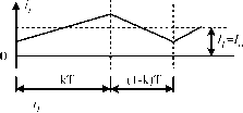
17.2.1 Fundamental Topologies The buck converter is a step-down converter and is shown in Fig. 17.1a. The typical output voltage and current waveforms are shown in Fig. 17.1b. The equivalent circuits during switch-on and switch-off periods are shown in Fig. 17.1c and d. Its output voltage and output current are: Vq = kVj and This converter may work in the discontinuous mode if the frequency/is smaU, conduction duty к is smaU, inductance L is smaU and the load current is high. The boost converter is a step-up converter and is shown in Fig. 17.2a. The typical output voltage and current waveforms are shown in Fig. 17.2b. The equivalent circuits during switch-on and switch-off periods are shown in Fig. 17.2c,d. Its output voltage and current are: and /0 = (1 - Щ The output voltage is higher than the input voltage. This converter may work in the discontinuous mode if the frequency / is smaU, conduction duty к is smaU, inductance L is smaU, and the load current is high. с r П v, FIGURE 17.1 Buck Converter: (a) circuit diagram; (b) waveforms of inductor voltage and current; (c) switch-on equivalent circuit; and (d) switch-off equivalent circuit. Rashid, M.H. Power Electronics: Circuits, Devices and Applications, Ije, © 1993, pp. 318, 321, 324, 327, 479. Adapted by permission of Pearson Education, Inc., Upper Saddle River, New Jersey. The buck-boost converter is a step-down/step-up converter, which is shown in Fig. 17.3a. The typical output voltage and current waveforms are shown in Fig. 17.3b. The equivalent circuits during switch-on and switch-off periods are shown in Fig. 17.3c,d. Its output voltage and current are: Vo=y, and Io = Ii When к is greater than 0.5, the output voltage can be higher than the input voltage. This converter may work in the discontinuous mode if the frequency / is small, conduction duty к is smaU, inductance L is smaU, and the load current is high. с R P V i, S Ф с R П V (V,) 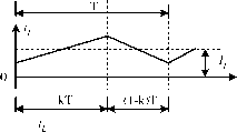
С R M V. С R П V. FIGURE 17.2 Boost converter: (a) circuit diagram; (b) waveforms of inductor voltage and current; (c) switch-on equivalent circuit; and (d) switch-off equivalent circuit. Rashid, M.H. Power Electronics: Circuits, Devices and Applications, 2/e, © 1993, pp. 318, 321, 324, 327, 479. Adapted by permission of Pearson Education, Inc., Upper Saddle River, New Jersey. 17.2.2 Developed Topologies The positive output Luo-converter is a step-down/step-up converter, which is derived from the buck-boost converter. It has one more inductor and capacitor, and is shown in Fig. 17.4a. The typical output voltage and current waveforms are shown in Fig. 17.4b. The equivalent circuits during switch-on and switch-off periods are shown in Fig. 17.4c,d. Its output voltage and current are: Vo = V, and Io = -jh When к is greater than 0.5, the output vohage can be higher than the input vohage. This converter may work in the discontinuous mode if the frequency / is small, к is small, inductance L is small, and the load current is high. 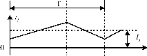 С R П V  FIGURE 17.3 Buck-boost converter: (a) circuit diagram; (b) waveforms of inductor voltage and current; (c) switch-on equivalent circuit; and (d) switch-off equivalent circuit. Rashid, M.H. Power Electronics: Circuits, Devices and Applications, 2/e, © 1993, pp. 318, 321, 324, 327, 479. Adapted by permission of Pearson Education, Inc., Upper Saddle River, New Jersey. A negative output Luo-converter is a negative output step-down/step-up converter, which is derived from the buck-boost converter. It has one more inductor and capacitor, and is shown in Fig. 17.5a. The typical output voltage and current waveforms are shown in Fig. 17.5b. The equivalent circuits during switch-on and switch-off periods are shown in Fig. 17.5c,d. Its output voltage and current (absolute value) are: Vn = - к I - к Vj and Io = --Ii When к is greater than 0.5, the output voltage can be higher than the input voltage. This converter may work in the 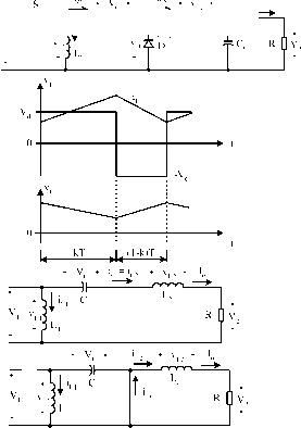 FIGURE 17.4 Positive output Luo-converter: (a) circuit diagram; (b) waveforms of inductor voltage and current; (c) switch-on equivalent circuit; (d) switch-off equivalent circuit. discontinuous mode if the frequency / is smaU, к is small, inductance L is smaU, and the load current is high. The double output Luo-converter is a double output step-down/step-up converter, which is derived from a P/O Luo-converter and an N/O Luo-converter. It has two conversion paths and two output voltages Vq and Vq . It is shown in Fig. 17.6a. The typical output voltage and current waveforms are shown in Fig. 17.6b. The equivalent circuits during switch-on and switch-off periods are shown in Fig. 17.6c,d. By carefully selecting the components we can obtain the output voltages and currents (absolute value) Io-=- l-k. When к is greater than 0.5, the output voltage can be higher than the input voltage. This converter may work in the discontinuous mode if the frequency / is smaU, к is small, inductance L is smaU, and the load current is high. 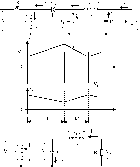 FIGURE 17.5 Negative ouput Luo-converter: (a) circuit diagram; (b) waveforms of inductor voltage and current; (c) switch-on equivalent circuit; and (d) switch-off equivalent circuit. The Cuk-converter is a negative output step-down/step-up converter, which is derived from the boost converter. It has one more inductor and capacitor, and is shown in Fig. 17.7a. The typical output voltage and current waveforms are shown in Fig. 17.7b. The equivalent circuits during switch-on and switch-off periods are shown in Fig. 17.7c,d. Its output voltage and current (absolute value) are: Vn = к I - к Vj and Io=--Ij When к is greater than 0.5, the output voltage can be higher than the input voltage. This converter may work in the discontinuous mode if the frequency / is smaU, к is smaU, inductance L is smaU, and the load current is high. 17.2.3 Transformer-Type Topologies The fly-back converter is a negative output step-up converter, which is shown in Fig. 17.8. The transformer turns ratio is N. If the transformer has never been saturated during operation. ---)\-ш^-гугу-у-у-,-: Ah. с . It, Ч ;ico (a) V 4>b i=-<l- icio 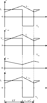
lis S Ч D Y d (l-k)T r nv li, L Vc - rW>-1( v., FIGURE 17.7 The Cuk converter: (a) circuit diagram; (b) waveforms of inductor voltage and current; (c) switch-on equivalent circuit; and (d) switch-off equivalent circuit. Rashid, M.H. Power Flectronics: Circuits, Devices and Applications, 2/e, © 1993, pp. 318, 321, 324, 327, 479. Adapted by permission of Pearson Education, Inc., Upper Saddle River, New Jersey. - v.
it works as a boost converter. Its output voltage and current (absolute value) are: VoNV, and loKrh This converter may work in the discontinuous mode if the frequency/is smaU, conduction duty к is small, inductance L о is smaU, and the load current is high. FIGURE 17.6 Double output Luo-converter: (a) circuit diagram; (b) The half-bridge converter is a Step-up converter, which is waveforms of inductor voltage and current; (c) switch-on equivalent shown in Fig. 17.9. There are two switches and one double circuit; and (d) switch-off equivalent circuit. secondary coils transformer required. The transformer turns 1 :N FIGURE 17.8 Flyback converter. Rashid, M.H. Power Electronics: Circuits, Devices and Applications, 2/e, © 1993, pp. 318, 321, 324, 327, 479. Adapted by permission of Pearson Education, Inc., Upper Saddle River, New Jersey. ratio is N. If the transformer has never been saturated during operation, it works as a half-bridge rectifier plus a buck converter. Its output voltage and current are: Vo = kNV, and h=h This converter may work in the discontinuous mode if the frequency/is smaU, conduction duty к is smaU, inductance L is smaU, and the load current is high. The forward converter is a step-up converter, which is shown in Fig. 17.10. The transformer turns ratio is N (usually N>\). If the transformer has never been saturated during operation, it works as a buck converter. The output voltage and current are: VokNVj and hh This converter may work in the discontinuous mode if the frequency/is small, conduction duty к is small, inductance L is small, and the load current is high. FIGURE 17.9 Half-bridge converter. Rashid, M.H. Power Electronics: Circuits, Devices and Applications, 2/e, © 1993, pp. 318, 321, 324, 327, 479. Adapted by permission of Pearson Education, Inc., Upper Saddle River, New Jersey. 1 :N С R П FIGURE 17.10 Forward converter. Rashid, M.H. Power Electronics: Circuits, Devices and Applications, 2/e, © 1993, pp. 318, 321, 324, 327, 479. Adapted by permission of Pearson Education, Inc., Upper Saddle River, New Jersey. Because of the effect of the parasitic elements, the voltage-conversion gain is hmited. Especially, when the conduction duty к is towards unity, the output voltage is sharply reduced. The voltage-hft technique is a popular method used in electronic circuit design. The application of this technique can effectively overcome the effect of the parasitic elements, and largely increase the voltage-transfer gain. In this section we introduce seven self-lift converters that are working in the continuous mode. P/O Luo self-lift converter; reverse P/O Luo self-lift converter; simplified P/O Luo self-lift converter; N/O Luo self-lift converter; Cuk self-lift converter; reverse Cuk self-lift converter; and enhanced self-lift circuit. The P/O Luo self-lift converter is shown in Fig. 17.11a. The typical output voltage and current waveforms are shown in Fig. 17.11b. The equivalent circuits during switch-on and S v., . T, (a) V, л
Ц кТ (l-k)T 1 (0) v, Jl Co X R 0 2 (d) 1li 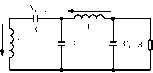 17.2.4 Seven (7) Self-Lift DC/DC Converters switch-off periods are shown in Fig. 17.1 lc,d. Its output voltage and current are: on and switch-off periods are shown in Fig. 17.12c,d. Its output voltage and current (absolute value) are: Vo=YVj and Io = (l-k)Ij The voltage transfer gain in the continuous mode is Vn It 1 Vo = YVj and Io = (l-k)Ij The voltage-transfer gain in the continuous mode is Vj I о l-k The variation ratio of the output voltage Vq in the continuous mode is Vj I о l-k The variation ratio of the output voltage VqIU the continuous mode is Avo/2 к I 8 = Vo SMsPCoL Avo/2 к The reverse P/O Luo self-lift converter is shown in Fig. 17.12a. Typical output voltage and current waveforms are shown in Fig. 17.12b. The equivalent circuits during switch- The simplified P/O Luo self-lift converter is shown in Fig. 17.13a. Typical output voltage and current waveforms are (a) Vl
iLi 3 Ч , C.lb R 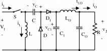 кТ J.(l-k)T (c) V, i:L - I (d) 1l: 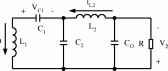
FIGURE 17.12 Negative output Luo self-lift converter: (a) circuit FIGURE 17.13 Simplified positive output Luo self-lift converter: (a) diagram; (b) waveforms of inductor voltage and current; (c) switch-on circuit diagram; (b) waveforms of inductor voltage and current; (c) equivalent circuit; and (d) switch-off equivalent circuit. switch-on equivalent circuit; and (d) switch-off equivalent circuit. 1 ... 31 32 33 34 35 36 37 ... 91 |
|||||||||||||||||||||||||||||||||||||||||||||||||||||||||||||||||||||||||||||||||||||||||||||||||||||||||||||||||||||||||||||||||
|
© 2026 AutoElektrix.ru
Частичное копирование материалов разрешено при условии активной ссылки |