 |
 |
 |
| Главная Журналы Популярное Audi - почему их так назвали? Как появилась марка Bmw? Откуда появился Lexus? Достижения и устремления Mercedes-Benz Первые модели Chevrolet Электромобиль Nissan Leaf |
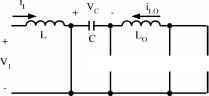
Главная » Журналы » Metal oxide semiconductor 1 ... 32 33 34 35 36 37 38 ... 91 shown in Fig. 17.13b. The equivalent circuits during switch-on and switch-off periods are shown in Fig. 17.13c,d. Its output voltage and current are: Vj and /о = (1 - k)h The voltage-transfer gain in the continuous mode is The variation ratio of the output voltage VqItv the continuous mode is г = IVq/I к 1 ~USpLoC,CoR The N/O Luo self-lift converter is shown in Fig. 17.14a. Typical output voltage and current waveforms are shown in Fig. 17.14b. The equivalent circuits during switch-on and switch-off periods are shown in Fig. 17.14c,d. Its output voltage and current (absolute value) are: Vn = - ; Vj and /о = (1 - The voltage-transfer gain in the continuous mode is The variation ratio of the output voltage VqIu the continuous mode is £ = Avo/2 Vo 128 PLoCiC,R The Cuk self-lift converter is shown in Fig. 17.15a. Typical output voltage and current waveforms are shown in Fig. 17.15b. The equivalent circuits during switch-on and switch-off periods are shown in Fig. 17.15c,d. Its output voltage and current (absolute value) are 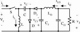
V, i,
FIGURE 17.14 Negative output Luo self-lift converter: (a) circuit diagram; (b) waveforms of inductor voltage and current; (c) switch-on equivalent circuit; and (d) switch-off equivalent circuit. The variation ratio of the output voltage Vq in the continuous mode is Vj and Io = (l- Щ The voltage-transfer gain in the continuous mode is Vo 128 pLoC,C,R Vj I о l-k The reverse Cuk self-lift converter is shown in Fig. 17.16a. Typical output voltage and current waveforms are shown in Fig. 17.16b. The equivalent circuits during switch-on and 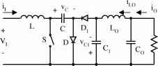 r v,
 С1Ф rQ v,
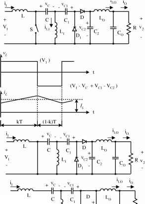 L A C2=r =r >r V FIGURE 17.16 The reverse Cuk self-lift converter: (a) circuit diagram; (b) waveforms of inductor voltage and current; (c) switch-on equivalent circuit; and (d) switch-off equivalent circuit. FIGURE 17.15 Cuk self-lift converter: (a) circuit diagram; (b) waveforms of inductor voltage and current; (c) switch-on equivalent circuit; and (d) switch-off equivalent circuit. switch-off periods are shown in Fig. 17.16c,d. Its output voltage and current are: Vo=Vj and Io = (l-k)Ij The voltage-transfer gain in the continuous mode is The enhanced self-lift converter is shown in Fig. 17.17a. Typical output voltage and current waveforms are shown in Fig. 17.17b. The equivalent circuits during switch-on and switch-off periods are shown in Fig. 17.17c,d. Its output voltage and current are: Vn = l-k. YVi and Io = jh Vj I о l-k The voltage-transfer gain in the continuous mode is M h 2-fc The variation ratio of the output voltage Vq in the continuous mode is The variation ratio of the output voltage VQin the continuous mode is г = Av/2 к I Vo USpLoCiCoR Avo/2 к I Vo 128 PLoCiCoR rY-V-Y-\ (a) V, 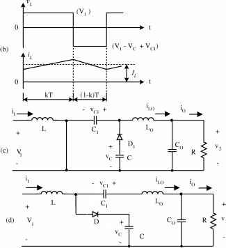 FIGURE 17.17 Enhanced self-lift converter: (a) circuit diagram; (b) waveforms of inductor voltage and current; (c) switch-on equivalent circuit; and (d) switch-off equivalent circuit. 17.2.5 Positive Output Luo-Converters The P/O Luo-converters perform the voltage conversion from one positive source to another positive load voltage using the voltage-lift technique. They work in the first quadrant with large voltage amplification, and their voltage-transfer gain is high. Five circuits are introduced in the literature. They are: elementary circuit; self-lift circuit; re-hft circuit; triple-lift circuit; and quadruple-hft circuit. An additional lift circuit can be derived from the formen-tioned circuits. In aU P/O Luo-converters, we define normalized inductance The P/O Luo elementary circuit is shown in Fig. 17.4a. Typical output voltage and current waveforms are shown in Fig. 17.4b. The equivalent circuits during switch-on and switch-off periods are shown in Fig. 17.4c,d. Its output voltage and current are: к I - к Vj and Io=-;-Ij к When к is greater than 0.5, the output voltage can be higher than the input voltage. The voltage-transfer gain in the continuous mode is к Vj I о l-k The variation ratio of the output voltage VqIii the continuous mode is 8 = Avo/2 Vo SMePCoL, This converter may work in the discontinuous mode if the frequency/is smaU, conduction duty к is small, inductance L is small, and the load current is high. The condition for the discontinuous mode is The output voltage in the discontinuous mode is Vo = Hl-k)V, with A l The P/O Luo self-lift circuit is shown in Fig. 17.11a. Typical output voltage and current waveforms are shown in Fig. 17.11b. The equivalent circuits during switch-on and switch-off periods are shown in Fig. 17.11c,d. Its output voltage and current are: Vo = - ; Vj and /о = (1 - Щ The voltage-transfer gain in the continuous mode is h - V + Lo and normalized impedance The variation ratio of the output vohage Vq in the continuous mode is 8 = Avo/2 к SMsPCoL, This converter may work in the discontinuous mode if the frequency/is small, conduction duty к is smaU, inductance L is smaU, and the load current is high. The condition for the discontinuous mode is The output vohage in the discontinuous mode is R 1 + k\l - k) 2/lJ / R 1 Vj with \fk /- > l2fL - l-k The P/O Luo re-lift circuit is shown in Fig. 17.18a. The typical output voltage and current waveforms are shown in Fig. 17.18b. The equivalent circuits during switch-on and switch-off periods are shown in Fig. 17.18c,d. Its output voltage and current are: Vn = - 2 l-k Vj and Iq = -I- It l-k 2 The voltage-transfer gain in the continuous mode is The variation ratio of the output voltage Vq in the continuous mode is Avo/2 к I Vo ШJ,pCoL, This converter may work in the discontinuous mode if the frequency/is small, conduction duty к is smaU, inductance L is smaU, and the load current is high. The condition for the discontinuous mode is Mj < /kz The output voltage in the discontinuous mode is Fig. 17.19b. The equivalent circuits during switch-on and switch-off periods are shown in Fig. 17.19c,d. Its output voltage and current are: The voltage-transfer gain in the continuous mode is Vj lo l-k The variation ratio of the output voltage VqIii the continuous mode is 8 = Avo/2 к I Vo SMrPCoL This converter may work in the discontinuous mode if the frequency/is smaU, conduction duty к is small, inductance L is smaU, and the load current is high. The condition for the discontinuous mode is The output voltage in the discontinuous mode is Vn = 3 + /c(l-/c)Jv. with d-- The P/O Luo quadruple-lift circuit is shown in Fig. 17.20a. The typical output voltage and current waveforms are shown in Fig. 17.20b. The equivalent circuits during switch-on and switch-off periods are shown in Fig. 17.20c,d. Its output voltage and current are: VojVj and lo-I, The voltage-transfer gain in the continuous mode is Mo = - = - = The variation ratio of the output vohage Vq in the continuous mode is 2 + k\l - k) 2/lJ R 2 Vj with Vk -> IfL - l-k The P/O Luo triple-lift circuit is shown in Fig. 17.19a. The typical output voltage and current waveforms are shown in Avo/2 к I Vo ~SM,pCoL, This converter may work in the discontinuous mode if the frequency/is smaU, conduction duty к is small, inductance L (a) V T 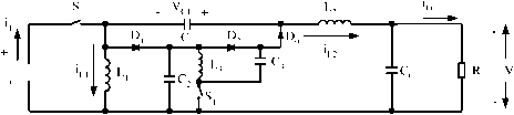 (-V,+V,) 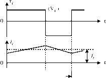 1 кТ (l-k)T (с) V, Cl + T I Cot Rp (d) i FIGURE 17.18 Positive output Luo re-lift converter: (a) circuit diagram; (b) waveforms of inductor voltage and current; (c) switch-on equivalent circuit; and (d) switch-off equivalent circuit. is small, and the load current is high. The condition for the The output voltage in the discontinuous mode is discontinuous mode is MQ<./2k 4 + k\l - k) 2/Lj Vj with Vk J- > у j-L 1 - К Li it С D3 s, Qr V 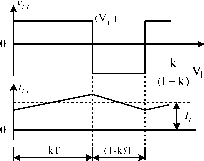 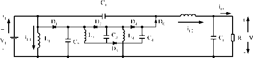 (d) i ± C, : L. 4 Or v, FIGURE 17.19 Positive output Luo triple-lift converter: (a) circuit diagram; (b) waveforms of inductor voltage and current; (c) switch-on equivalent circuit; and (d) switch-off equivalent circuit. Summary for all P/O Luo-converters: Vi Iq the self-lift circuit, j = 2 for the re-lift circuit, j = 3 for the triple-hft circuit, j = 4 for the quadruple-lift circuit, and so on. The voltage-transfer gain is To write common formulas for all circuits parameters, we define that subscript j = 0 for the elementary circuit, j = 1 for fcftO)[j + fe(j)] > l-k (a) V, Dl 2 D4 Рб Or v
V CI +
Qr v FIGURE 17.20 Positive output Luo quadruple-lift converter: (a) circuit diagram; (b) waveforms of inductor voltage and current; (c) switch-on equivalent circuit; and (d) switch-off equivalent circuit. The variation ratio of the output vohage is Avo/2 к 1 ~ Vo ~ ЩРСоЬ^ The condition for the discontinuous mode is /с[1+ВД]+/г(;) Mf 2 The output vohage in the discontinuous mode is where is the Hong fimction. 0 j>l 1 if jO 17.2.6 Simplified Positive Output Luo-Converters By carefully checking the P/O Luo-converters we can see that there are two switches required from the re-lift circuit. In order to use only one switch in aU P/O Luo-converters, we modify the circuits. In this section we introduce the foUowing four circuits: simplified self-hft circuit; simplified re-lift circuit; simplified triple-hft circuit; and the simplified quadruple-lift circuit. An additional lift circuit can be derived from the forementioned circuits. In aU S P/O Luo-Converters, we define -Jl normalized impedance. The S P/O Luo self-lift circuit is shown in Fig. 17.13a. The typical output voltage and current waveforms are shown in Fig. 17.13b. The equivalent circuits during switch-on and switch-off periods are shown in Fig. 17.13c,d. Its output voltage and current are Vj and = (1 - k)Ij The voltage-transfer gain in the continuous mode is Ms= - = - = The S P/O Luo re-lift circuit is shown in Fig. 17.21a. The typical output voltage and current waveforms are shown in Fig. 17.21b. The equivalent circuits during switch-on and switch-off periods are shown in Fig. 17.21c,d. Its output voltage and current are VojVj and loI, The voltage-transfer gain in the continuous mode is The variation ratio of the output voltage VqIU the continuous mode is Avo/2 Vn 128/UoCiCoi This converter may work in the discontinuous mode if the frequency/is smaU, conduction duty к is small, inductance L is smaU, and the load current is high. The condition for the discontinuous mode is Mj < ./kz The output voltage in the discontinuous mode is Vo = Vi I о i-k 2 + k\l - k) 2/Lj V, with >ЯД>: The variation ratio of the output voltage Vq in the continuous mode is aw2 к Vo USpLoCiCoR This converter may work in the discontinuous mode if the frequency/is small, conduction duty к is smaU, inductance L is small, and the load current is high. The condition for the discontinuous mode is The S P/O Luo triple-lift circuit is shown in Fig. 17.22a. The typical output voltage and current waveforms are shown in Fig. 17.22b. The equivalent circuits during switch-on and switch-off periods are shown in Fig. 17.22c,d. Its output voltage and current are 3 I - к Vn = --tVj and Io = --Ij The voltage-transfer gain in the continuous mode is Ms < VkJ Vi I о l-k The output vohage in the discontinuous mode is The variation ratio of the output vohage Vq in the continuous mode is 1 + k{\ - k) 2/lJ Vj with -s/k 2/1 - 1 - fc e = Avo/2 к 1 Vo ~mpLoC,CoR 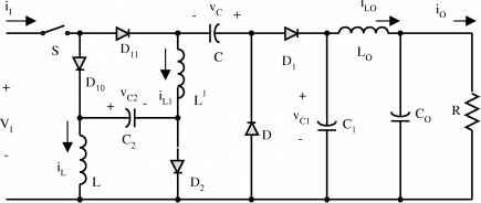 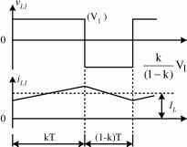 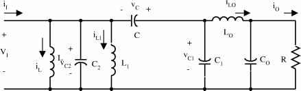 i,=0 (d) V,
FIGURE 17.21 Simplified positive output Luo re-lift converter: (a) circuit diagram; (b) waveforms of inductor voltage and current; (c) switch-on equivalent circuit; and (d) switch-off equivalent circuit. (a) V,
кТ (l-k)T , (C) V, A ci 1 ... 32 33 34 35 36 37 38 ... 91 |
||||||||||||||||||||||||||||||||||||||||||||||||||||||||||||||||||||||||||||||||||||||||||||||||||||||||||||||||
|
© 2026 AutoElektrix.ru
Частичное копирование материалов разрешено при условии активной ссылки |