 |
 |
 |
| Главная Журналы Популярное Audi - почему их так назвали? Как появилась марка Bmw? Откуда появился Lexus? Достижения и устремления Mercedes-Benz Первые модели Chevrolet Электромобиль Nissan Leaf |
Главная » Журналы » Metal oxide semiconductor 1 ... 33 34 35 36 37 38 39 ... 91 This converter may work in the discontinuous mode if the frequency/is smaU, conduction duty к is smaU, inductance L is smaU, and the load current is high. The condition for the discontinuous mode is To write common formulas for aU circuit parameters, we define that subscript j = 1 for the self-lift circuit, j = 2 for the re-hft circuit, j = 3 for the triple-lift circuit, j = 4 for the quadruple-lift circuit, and so on. The voltage-transfer gain is l-k The output voltage in the discontinuous mode is 3 + k\l - k) 2/Lj / 3R 3 Vj with Vk /- > 2fL - l-k The S P/O Luo quadruple-lift circuit is shown in Fig. 17.23a. The typical output voltage and current waveforms are shown in Fig. 17.23b. The equivalent circuits during switch-on and switch-off periods are shown in Fig. 17.23c,d. Its output voltage and current are Vo=YVj and Io=-h The voltage-transfer gain in the continuous mode is Vj I о l-k The variation ratio of the output voltage is Avo/2 к 1 Vo mpLoQCoR The condition for the discontinuous mode is The output voltage in the discontinuous mode is Vo-j = j + k\l-ky- Using these circuits is easy to convert a 24-V input source voltage into a 1000-V output load-voltage. Some applications in insulation testing have been reported. The variation ratio of the output voltage Vq in the continuous mode is 8 = Avo/2 к ~l2SpLoCiCoR This converter may work in the discontinuous mode if the frequency/is smaU, conduction duty к is smaU, inductance L is smaU, and the load current is high. The condition for the discontinuous mode is MQ<2k The output voltage in the discontinuous mode is 4 + k\l - k) 2/Lj 2R 4 Vj with kl->Y, Summary for aU S P/O Luo-converters: 17.3 Negative Output Luo-Converters The N/O Luo-converters perform voltage conversion from positive to negative voltages using the voltage-lift technique. They work in the third quadrant with large voltage amplification, and their voltage-transfer gain is high. Five circuits are introduced in the literature. They are: elementary circuit; self-lift circuit; re-lift circuit; triple-lift circuit; and quadruple-lift circuit. An additional lift circuit can be derived from the forementioned circuits. In aU N/O Luo-Converters, we define normalized impedance The N/O Luo elementary circuit is shown in Fig. 17.5a. The typical output voltage and current waveforms are shown in Fig. 17.5b. The equivalent circuits during switch-on and LO Iq ->- C4 L<a)
1 кТ (l-k)T 1
switch-off periods are shown in Fig. 17.5c,d. Its output vohage is small, and the load current is high. The condition for the and current (the absolute value) are discontinuous mode is к Vn = Vj and Io = -Ij M,<VkJ When к is greater than 0.5, the output voltage can be higher than the input voltage. The voltage-transfer gain in the continuous mode is The output voltage in the discontinuous mode is R Vn = I + k\l - k) 2/Lj Vj with Vk /- > 2fL - l-k . r , , . , . The N/O Luo re-lift circuit is shown in Fig. 17.24a. The The variation ratio of the output voltage Vn m the continuous . i . . i. i . r i . F & о typical output vohage and current waveforms are shown m Fig. 17.24b. The equivalent circuits during switch-on and switch-off periods are shown in Fig. 17.24c,d. Its output voltage and current (the absolute value) are Avo/2 к I Vo 128 PCCqLoR Vn = - 2 l-k Vj and Io=--Ij This converter may work in the discontinuous mode if the , - i i - frequency/is smaU, conduction duty к is smaU, inductance L is smaU, and the load current is high. The condition for the , r л i J. . J . The voltage-transier gam m the continuous mode is discontinuous mode is о о < к The output voltage in the discontinuous mode is Vj I о l-k The variation ratio of the output voltage VqUv the continuous mode is V = .-<:)V, i.h Ji Avo/2 к Vo 128 PCCqLoR The N/O Luo self-lift circuit is shown in Fig. 17.14a. The his converter may work in the discontinuous mode if the typical output voltage and current waveforms are shown in frequency/is smaU, conduction duty к is small, inductance L Fig. 17.14b. The equivalent circuits during switch-on and ц^ d the load current is high. The condition for the switch-off periods are shown in Fig. 17.14c,d. Its output discontinuous mode is voltage and current (the absolute value) are Vj and Io = (l- k)Ij Mj < ./k The output voltage in the discontinuous mode is The voltage-transfer gain in the continuous mode is Vo = 2 + kHl - k) 2/lJ V, with Yi-k The variation ratio of the output vohage Vq in the continuous The N/O Luo triple-lift circuit is shown in Fig. 17.25a. The mode is typical output voltage and current waveforms are shown in Fig. 17.25b. The equivalent circuits during switch-on and Avq/2 к I switch-off periods are shown in Fig. 17.25c,d. Its output Vq ~ 128 PCCqLqR voltage and current (the absolute value) are This converter may work in the discontinuous mode if the frequency/is smaU, conduction duty к is smaU, inductance L 3 I - к Vj and Iq =-Ij 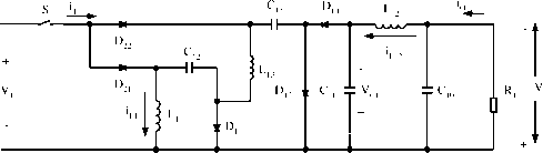 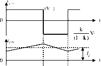 1 кТ (l-k)T 1 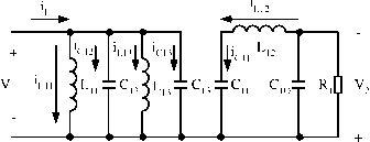 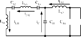 FIGURE 17.24 Negative output Luo re-lift converter: (a) circuit diagram; (b) waveforms of inductor voltage and current; (c) switch-on equivalent circuit; and (d) switch-off equivalent circuit. The voltage-transfer gain in the continuous mode is The variation ratio of the output voltage Vq in the continuous mode is This converter may work in the discontinuous mode if the frequency/is smaU, conduction duty к is small, inductance L is smaU, and the load current is high. The condition for the discontinuous mode is Avo/2 к Vo ~ 128 PCCqLoR D ± C ±C Dr. 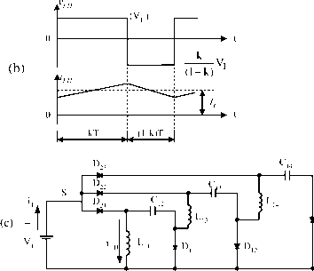
 FIGURE 17.25 Negative output Luo triple-lift converter: (a) circuit diagram; (b) waveforms of inductor voltage and current; (c) switch-on equivalent circuit; and (d) switch-off equivalent circuit. The output vohage in the discontinuous mode is 3 + k\l - k) 2/Lj with Vk > 2fL - l-k The N/O Luo quadruple-lift circuit is shown in Fig. 17.26a. The typical output voltage and current waveforms are shown in Fig. 17.26b. The equivalent circuits during switch-on and switch-off periods are shown in Fig. 17.26c,d. Its output voltage and current (the absolute value) are Vo = YVj and Io=Ii The voltage-transfer gain in the continuous mode is Vn h Vj Io l-k (a) + D21 -N- 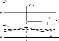 > t U--,ULJ 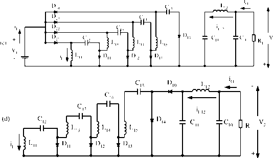 FIGURE 17.26 Negative output Luo quadruple-lift converter: (a) circuit diagram; (b) waveforms of inductor voltage and current; (c) switch-on equivalent circuit; and (d) switch-off equivalent circuit. The variation ratio of the output voltage Vq in the continuous is smaU, and the load current is high. The condition for the mode is discontinuous mode is Avo/2 к 1 Vo USpCCoLoR MQ<2k The output voltage in the discontinuous mode is This converter may work in the discontinuous mode if the Vq = frequency/is small, conduction duty к is smaU, inductance L 4 + k\l - k) 2/Lj 2R 4 V, with kl->Y, Summary for all N/O Luo-converters: M = - = z =- R = To write common formulas for all circuits parameters, we define that subscript j = 0 for the elementary circuit, j = I for the self-lift circuit, j = 2 for the re-lift circuit, j = 3 for the triple-lift circuit, j = 4 for the quadruple-lift circuit, and so on. The voltage-transfer gain is The variation ratio of the output voltage is e - Avo/2 Vo 128 fCCoLoR The condition for the discontinuous mode is k[i+h(j)]j+h(j) % > 1 The output voltage in the discontinuous mode is 1 - к where h(j) = 0 if j>l 1 if j = 0 17 л л Double Output Luo-Converters Five circuits are introduced in the literature: elementary circuit; self-lift circuit; re-lift circuit; triple-lift circuit; and quadruple-lift circuit. An additional lift circuit can be derived from the forementioned circuits. In aU D/O Luo-converters, each circuit has two conversion paths - a positive conversion path and a negative conversion path. The positive path prefers P/O Luo-converters, and the negative path prefers N/O Luo-converters. We define normalized inductance L = l1l2/l1 + l2 normalized impedance zj = R/fL for the positive path, and normahzed impedance = Ri/fLu the negative path. We usually purposely select R = Ri and L = Ьц, so that we have The D/O Luo elementary circuit, shown in Fig. 17.6a was introduced in Section 17.2.2. The typical output voltage and current waveforms are shown in Fig. 17.6b. The equivalent circuits during switch-on and switch-off periods are shown in Fig. 17.6c,d. Its output voltages and currents (absolute values) are: Vo = \VnJ = I --I When к is greater than 0.5, the output voltage can be higher than the input voltage. The voltage-transfer gain in the continuous mode is is the Hong function. Using these circuits it is easy to convert a 24-V input source-voltage into a -1000-V output load-voltage. Some applications in insulation testing have been reported. 17.4 Double Output Luo-Converters Double output Luo-converters perform the voltage conversion from positive to positive and negative voltages simultaneously using the voltage-hft technique. They work in the first and third quadrants with large voltage amplification, and their voltage-transfer gain is high. There are two groups of these converters: double output Luo-converters (D/O Luo-converters); and simplified double output Luo-converters (S D/O Luo-Converters). We wiU introduce them one by one. The variation ratio of the output voltage Vq in the continuous mode is Avo/2 к l + Уо+ ePCoL2 The variation ratio of the output voltage Vq in the continuous mode is e = AvoJ2 128/3CnQoIi2ii This converter may work in the discontinuous mode if the frequency/is smaU, conduction duty к is small, inductance L is small, and the load current is high. The condition for the discontinuous mode is Me < к The output voltages in the discontinuous mode are VoVo+\Vo.\kil-k)Vj with M>Y A D/O Luo self-lift circuit is shown in Fig. 17.27a. The typical output voltage and current waveforms are shown in Fig. 17.27b. The equivalent circuits during switch-on and switch-off periods are shown in Fig. 17.27c,d. Its output voltages and currents (absolute values) are: with kzN 1 A D/O Luo re-lift circuit is shown in Fig. 17.28a. The typical output voltage and current waveforms are shown in Fig. 17.28b. The equivalent circuits during switch-on and switch-off periods are shown in Fig. 17.28c,d. Its output voltages and currents (absolute values) are: Io- = Vo+ = The voltage-transfer gain in the continuous mode is Mj, = /о- = (1 - k)Kj The voltage-transfer gain in the continuous mode is The variation ratio of the output voltage Vq in the continuous mode is Mc = 0+ I o- Vj Vj l-k Ato+/2 к The variation ratio of the output voltage Vq in the continuous mode is The variation ratio of the output voltage Vq in the continuous mode is AvoJ2 к I e = Avo-/2 к 128/3CnQoIi2i The variation ratio of the output voltage Vq in the continuous mode is e = Avo-/2 к This converter may work in the discontinuous mode if the frequency/is smaU, conduction duty к is small, inductance L is smaU, and the load current is high. The condition for the discontinuous mode is 128/3 CnQoIii This converter may work in the discontinuous mode if the frequency/is small, conduction duty к is smaU, inductance L is smaU, and the load current is high. The condition for the discontinuous mode is Mj < /kz The output voltages in the discontinuous mode are Vo=Vo+ = \VoJ = 2 + k\l-kff[Vj] Ms < VkJ The output voltages in the discontinuous mode are Vo=Vo+ = \VoJ = l + k\l-k)f with A D/O Luo triple-lift circuit is shown in Fig. 17.29a. The typical output voltage and current waveforms are shown in ci + .j>r>r>r\
кТ (l-k)T 1 HI-orvY4.
(c) S: ON; Dq, В^: OFF HI-- -н Ф Co Rh Y -11 ici rvv-v-4 (d) S: OFF; Dq, D: ON FIGURE 17.27 Double output Luo self-lift converter: (a) circuit diagram; (b) waveforms of inductor voltage and current; (c) switch-on equivalent circuit; and (d) switch-off equivalent circuit. 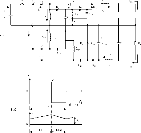 - V + L2 V, LI L, Соф Rp V, i 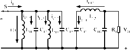 (с) S: ON; Dq: OFF (c) S: ON; Diq: OFF 1t19 L3 Ic Соф RU 4i (d)S:OFF; Dq: ON (d)S:OFF;Dio: ON 1 ... 33 34 35 36 37 38 39 ... 91 |
|||||||||||||||||||||||||||||||||||||||||||||||||||||||||||||||||||||||||||||||||||
|
© 2026 AutoElektrix.ru
Частичное копирование материалов разрешено при условии активной ссылки |