 |
 |
 |
| Главная Журналы Популярное Audi - почему их так назвали? Как появилась марка Bmw? Откуда появился Lexus? Достижения и устремления Mercedes-Benz Первые модели Chevrolet Электромобиль Nissan Leaf |
Главная » Журналы » Metal oxide semiconductor 1 ... 34 35 36 37 38 39 40 ... 91 Fig. 17.29b. The equivalent circuits during switch-on and and switch-off periods are shown in Fig. 17.29c,d. Its output voltages and currents (absolute values) are: The voltage-transfer gain in the continuous mode is 0- = -!:- The voltage-transfer gain in the continuous mode is Mj=- Vj Vj l-k The variation ratio of the output voltage Vq in the continuous mode is 8MpCoL, The variation ratio of the output vohage Vq in the continu- The variation ratio of the output voltage Vq- in the continuous mode is ous mode is Avo+/2 , 8MtPCoL2 Avo-/2 128/3C Qoii2-Ri The variation ratio of the output voltage Vq in the continu- This converter may work in the discontinuous mode if the ous mode is frequency/is smaU, conduction duty к is small, inductance L is small, and the load current is high. The condition for the Avq /2 к 1 discontinuous mode is 12S PC C L R, This converter may work in the discontinuous mode if the frequency /is small, conduction duty к is small inductance L j discontinuous mode is small, and the load current is high. The condition for the discontinuous mode is Mj < 3kZf, Vo = Vo+\Vo.\ 4 + k\l-k) with The output voltages in the discontinuous mode are Vo=Vo+ = \VoJ = 3 + k\l - k) with V2k>YZr Summary for all D/O Luo-converters: M = - L1L2 A D/O Luo quadruple-lift circuit is shown in Fig. 17.30a. The typical output voltage and current waveforms are shown in so that Fig. 17.30b. The equivalent circuits during switch-on and switch-off periods are shown in Fig. 17.30c,d. Its output voltages (absolute values) are: To write common formulas for aU circuit parameters, we % - - yo = \Vo-\=Y4 define that subscript j = 0 for the elementary circuit, j = I for the self-lift circuit, j = 2 for the re-lift circuit, j = 3 for the 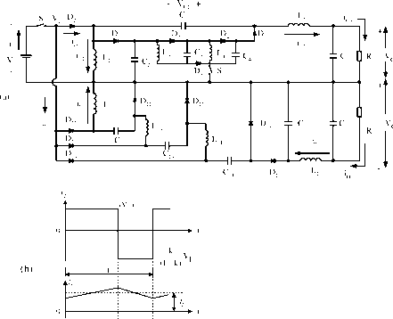 1 кТ (l-k)T 1 D4 Do D :p C :;:c, D4 , Dq 2 I0+ -I D,n Ч2 -II-1- d2 D4 H Ф c П r v - -b -15 10 (b) U  кТ i (l-k)T ci + ibiJi -J-1-1 (d) i, Ч2 I- l D, L triple-lift circuit, j = 4 for the quadruple-lift circuit, and so on. The voltage-transfer gain is M..= The variation ratio of the output vohage Vq in the continuous mode is Avo+/2 k The variation ratio of the output voltage Vq in the continuous mode is Avo-/2 к The condition for the discontinuous mode is path. We usually select R = Ri and L = L, so that we have = = z . The S D/O Luo self-lift circuit is shown in Fig. 17.31a. The typical output voltage and current waveforms are shown in Fig. 17.31b. The equivalent circuits during switch-on and switch-off periods are shown in Fig. 17.31c,d. Its output voltages and currents (absolute values) are: Vj 7о+ = (1-ад+ Jo- = (1 - k)Ij The voltage-transfer gain in the continuous mode is Mc = Vj Vj l-k The variation ratio of the output voltage Vqj in the continuous mode is The output voltage in the discontinuous mode is where is the Hong function. Using these circuits is easy to convert a 24-V input source-voltage into a iblOOO-V output load-voltage. Some applications in insulation testing have been reported. 17.4.2 Simplified Double Output Luo-Converters By carefully checking P/O Luo-converters we can see that there are two switches required from the re-lift circuit. In order to use only one switch in aU P/O Luo-converters, we modify the circuits. In this section we introduce the foUowing four circuits: simplified self-hft circuit; simplified re-lift circuit; simplified triple-hft circuit; and simplified quadruple-lift circuit. An additional lift circuit can be derived from the forementioned circuits. In all S P/O Luo-converters, we define normalized impedance as zj = r/fL for the positive path and normalized impedance as z = Ri/fL for the negative Avo/2 к 1 + Уо+ nPCCoLR The variation ratio of the output voltage Vq in the continuous mode is e = Avo-12 к l2SpC C,oLuRi This converter may work in the discontinuous mode if the frequency/is small, conduction duty к is small, inductance L is smaU, and the load current is high. The condition for the discontinuous mode is Ms<kJ Output voltages in the discontinuous mode are 0=0+ = 10-1 = 1 + k\l - k) with > An S D/O Luo re-lift circuit is shown in Fig. 17.32a. The typical output voltage and current waveforms are shown in Fig. 17.32b. The equivalent circuits during switch-on and ci + T 2 =F Co D R Vo 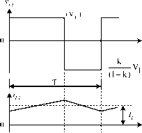 I кТ I (l-k)T I 10 Vr 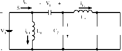 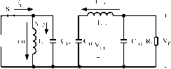 (c) S: ON; Dq: OFF (c) S: ON; Diq: OFF It 9 It 19
(d) S: OFF; Dq: ON (d) S: OFF; В^: ON FIGURE 17.31 Simplified double output Luo self-lift converter: (a) circuit diagram; (b) waveforms of inductor voltage and current; (c) switch-on equivalent circuit; and (d) switch-off equivalent circuit. switch-off periods are shown in Fig. 17.32c,d. Its output voltages and currents (absolute values) are: Vo+ = \VoJ=yj Vr Io+=- F. L. Luo, H. Ye and M. H. Rashid The vohage-transfer gain in the continuous mode is Vo+ \Vo-\ 3 Mr = V, Vi l-k The vohage-transfer gain in the continuous mode is The variation ratio of the output voltage Vqj in the continuous mode is Avo+/2 к I The variation ratio of the output voltage Vq in the continuous mode is The variation ratio of the output voltage Vqj in the continuous mode is At;o+/2 к I e = Avo-/2 к I 128/3CnQoIi2ii The variation ratio of the output voltage Vq in the continuous mode is This converter may work in the discontinuous mode if the frequency/is smaU, conduction duty к is small, inductance L is smaU, and the load current is high. The condition for the discontinuous mode is e = Avo-/2 к Vo l2SpCnC,oLnRi This converter may work in the discontinuous mode if the frequency/is small, conduction duty к is smaU, inductance L is smaU, and the load current is high. The condition for the discontinuous mode is Mj < Vkz. Output voltages in the discontinuous mode are Mt < Output voltages in the discontinuous mode are VoVo+WoJ 3 + kHl-k)=f with Vn Vo+ WnJ 2 + k\l-kf-f with л/к^> An S D/O Luo triple-lift circuit is shown in Fig. 17.33a. The typical output voltage and current waveforms are shown in Fig. 17.33b. The equivalent circuits during switch-on and switch-off periods are shown in Fig. 17.33c,d. Its output voltages and currents (absolute values) are: An S D/O Luo quadruple-lift circuit is shown in Fig. 17.34a. The typical output voltage and current waveforms are shown in Fig. 17.34b. The equivalent circuits during switch-on and switch-off periods are shown in Fig. 17.34c,d. Its output voltages and currents (absolute values) are: Vo+ = \VoJ= - Vi Io+ = Vo+ = \VoJ=jyi Vr Io+=- The vohage-transfer gain in the continuous mode is lo-=- Mn=- Ч IL3 q (l-k) кТ (l-k)T 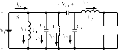 Соф RDo.Vi-k i 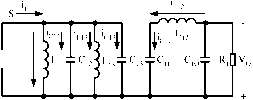 (c) S: ON; Dq: OFF (c) S: ON; Diq: OFF
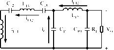 (d) S: OFF; Dq: ON (d) S: OFF; Diq: ON FIGURE 17.32 Simplified double output Luo re-lift converter: (a) circuit diagram; (b) waveforms of inductor voltage and current; (c) switch-on equivalent circuit; (d) switch-off equivalent circuit. The variation ratio of the output vohage Vqj in the continu- The variation ratio of the output vohage Vq in the continuous mode is ous mode is AvoJ2 к 1 Уо+ I28PC2C0L2R e = Avo /2 к 1 c! I 1 I кТ I (l-k)T , j J - -I-Ih- iL12 oJ .9! I 70 V, s v. d Сз jl3c, Jl,c it 19 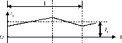 1 кТ (l-k)T 1 - v, + -1-I Vhi-I Vhi- QR V -15 10 - v., + io. -I d Щ dI -1-I HI-I Ihi- , C3 jl3c, Jl,C3 iLiiTiL HI-Пцз Cl2 [ , Do T фс, QR o. This converter may work in the discontinuous mode if the frequency/is small, conduction duty к is smaU, inductance L is smaU, and the load current is high. The condition for the discontinuous mode is Output voltages in the discontinuous mode are with 1 -fc Summary for all S D/O Luo-converters:
Li - 111 R - Rl Zjv+ - so that = Zjv+ = Zjv To write common formulas for all circuits parameters, subscript j = 1 for the self-hft circuit, j = 2 for the re-hft circuit, j = 3 for the triple-lift circuit, j = 4 for the quadruple-lift circuit, and so on. The voltage-transfer gain is The variation ratio of the output voltage Vq in the continuous mode is AvoJ2 к Уо+ npCCoLR The variation ratio of the output voltage Vq in the continuous mode is Avo-12 128/3CnCioIi2ii The condition for the discontinuous mode is 17.5 Multiple-Quadrant Operating Luo-Converters Multiple-quadrant operating converters are second-generation converters. These converters usually perform between two voltage sources and Y. Voltage source Y is the positive voltage and voltage Y is the load voltage. In the investigation both voltages are constant voltage, as Y and Y are constant values, the voltage-transfer gain is constant. Our research wiU concentrate on the working current, minimum conduction duty /Cjin the power transfer efficiency ц. Multiple-quadrant operating Luo-converters are second-generation converters and they have three modes: two-quadrant dc/dc Luo-converter in forward operation; two-quadrant dc/dc Luo-converter in reverse operation; and four-quadrant dc/dc Luo-converter. The two-quadrant dc/dc Luo-converter in forward operation has been derived from the positive output Luo-converter. It performs in the first quadrant Qj and the second quadrant Qii corresponding to the dc motor forward operation in motoring and regenerative braking states. The two-quadrant dc/dc Luo-converter in reverse operation has been derived from the negative output Luo-converter. It performs in the third quadrant Qm and the fourth quadrant Qiv corresponding to the dc motor reverse operation in motoring and regenerative braking states. The four-quadrant dc/dc Luo-converter has been derived from the double output Luo-converter. It performs four-quadrant operation corresponding to the dc motor forward and reverse operation in motoring and regenerative braking states. In the foUowing analysis the input source and output load are usually constant voltages as shown by Y and Y2. Switches and s2 in this diagram are power MOSFET devices, and they are driven by a pulsewidth-modulated (PWM) switching signal with repeating frequency f and conduction duty k. In this paper the switch-repeating period is T = 1 , so that the switch-on period is /сТ and switch-off period is (1 - /с)Т. The equivalent resistance is R for each inductor. During switch-on the voltage drop across the switches and diodes is V5 and У^, respectively. The output vohage in the discontinuous mode is Using these circuits is easy to convert a 24-V input source-voltage into a iblOOO-V output load-voltage. Some applications in insulation testing have already been published. 17.5.1 Two-Quadrant DC/DC Luo-Converter in forward Operation An F 2Q Luo-converter shown in Fig. 17.35, has two switches with two passive diodes, two inductors and one capacitor. The 1 ... 34 35 36 37 38 39 40 ... 91 |
|
© 2026 AutoElektrix.ru
Частичное копирование материалов разрешено при условии активной ссылки |