 |
 |
 |
| Главная Журналы Популярное Audi - почему их так назвали? Как появилась марка Bmw? Откуда появился Lexus? Достижения и устремления Mercedes-Benz Первые модели Chevrolet Электромобиль Nissan Leaf |
Главная » Журналы » Metal oxide semiconductor 1 ... 35 36 37 38 39 40 41 ... 91 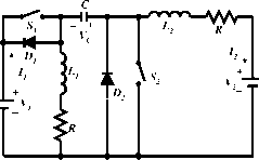 FIGURE 17.35 Forward two-quadrant operating Luo-converter. Po Vih V, l-k V, The variation ratio of capacitor vohage is Avc/2 (1 - k)l2 2fc(v,-Rl2 source vohage (V) and load voltage (v2) are usually considered as constant voltages. The load can be a battery or motor back-electromotive force (EMF). For example, the source voltage is 42 V and load voltage is +14 V. There are two modes of operation: (1) Mode A (Quadrant I) - electrical energy is transferred from source side V to load side V2; and (2) Mode В (Quadrant II) - electrical energy is transferred from load side v2 to source side V. Mode A. The equivalent circuits during switch-on and switch-off periods are shown in Fig. 17.36a,b. The typical output voltage and current waveforms are shown in Fig. 17.36c. Output current I2 is 4 = -;- h and V,-Vs-V-V2- The minimum conduction duty к corresponding to /2 = 0 is The variation ratio of inductor current is Ain/2y,-Vs-Rh 2/1,/, The variation ratio of inductor current ii2 is A/W2 ,V,-Vs-Rh c2 = =k- 2fhh The variation ratio of the diode current is AW2 - - Ji .2 1 -Vs-RI h,+h 2fL(I,+I,) 2/1/, If the diode current becomes zero before S, switches on again, the converter works in a discontinuous region. The condition is Cd2 - 1> that is, min - Vi + V,-Vs- Vo 2/17, V-V,- RI, У 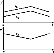 (a) (b) (c) FIGURE 17.36 Mode A: (a) switch on; (b) switch off; and (c) waveforms with enlarged variations. The power transfer efficiency
M I II-WMMrn B, I - + . h R V. 1, 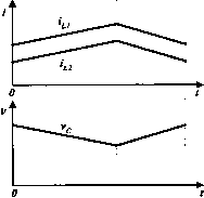 (a) (b) (c) figure 17.37 Mode B: (a) switch on; (b) switch off; and (c) waveforms with enlarged variations. Mode B. The equivalent circuits during switch-on and switch-off periods are shown in Fig. 17.37a,b. The typical output voltage and current waveforms are shown in Fig. 17.37c. I - к Output current II is I = ---12 and К V-iV + Vs + Vj,)-Rlz-Г + yl-k к The minimum conduction duty fc corresponding to = 0 is Vl + У2 + V5 + The power transfer efficiency Pi V,I, 1-fc The variation ratio of capacitor vohage is Аус/2 fc/i --V-RL (1 - fc)J The variation ratio of inductor current гц is A/ii/2 In 2/IiJi The variation ratio of inductor current is 2fL,I, The variation ratio of the diode current ij,; is AW2 \V-li- ,22-S-M2 L,D1 - T-- - к -- к 2fLI, If the diode current becomes zero before s2 switches on again, the converter works in a discontinuous region. The condition is lt)i = 1, that is. 17.5.2 Two-Quadrant DC/DC Luo-Converter in Reverse Operation The R 2Q Luo-converter shown in Fig. 17.38 has two switches with two passive diodes, two inductors and one capacitor. The source voltage (У^) and load voltage (v2) are usually considered as constant voltages. The load can be a battery or motor back-electromotive force (EMF). For example, the source voltage is 42 V and load voltage is -14 V. There are two modes of operation: (1) Mode С (Quadrant III) - electrical energy is transferred from source side to load side - V2, and (2) Mode D (Quadrant IV) - electrical energy is transferred from load side - v2 to source side V. 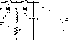 figure 17.38 Reverse two-quadrant operating Luo-converter. 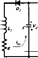 npQT-Wy- 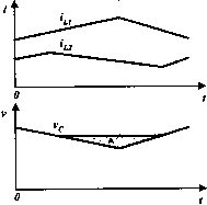 (a) (b) (c) figure 17.39 Mode C: (a) switch on; (b) switch off; and (c) waveforms with enlarged variations. Mode C. The equivalent circuits during switch-on and switch-off periods are shown in Fig. 17.39a,b. The typical output voltage and current waveforms are shown in Fig. 17.39c. Output current I2 is Ух-Уз-Ув-Уг- 1 1 - fc + fc(l - fc) fc The minimum conduction duty fc corresponding to = 0 is in - V + V,-Vs- Vr> The power transfer efficiency Po Угк Pi УЛ Vs + yp к RI, The variation ratio of capacitor voltage is 1 -fc A%/2 [l-fc 1 (1-kfj The variation ratio of inductor current is , MlJ2 jV,-Vs-Rh 2/1,/, and the variation ratio of inductor current ij), A/D2/2 V-Vs-RI 4d2 - Ci - In 2fL,I, The variation ratio of inductor current is I2 I6PCL2 If the diode current becomes zero before switches on again, the converter works in a discontinuous region. The condition is I2 = ly that is. k = - 2fL,I, V,-Vs- RI, Mode D. The equivalent circuits during switch-on and switch-off periods are shown in Fig. 17.40a,b. The typical output voltage and current waveforms are shown in Fig. 17.40c. I - к Output current II is = ---12 and Уг - {Уу + ys+ Ув) 1 - fc - + fc(l - fc) 1 - fc The minimum conduction duty fc corresponding to /, = 0 is y, + ys + Уо Knin - y+y. + Vs + Br 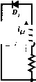 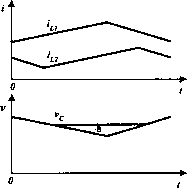 (a) (b) (c) figure 17.40 Mode D: (a) switch on; (b) switch off; (c) waveforms with enlarged variations. The power transfer efficiency The variation ratio of inductor current is Aii2/2 1 - к + Уд , RI, 1 / к + (1 - kf \1 - к The variation ratio of capacitor vohage is Avc/2 V + к fc(l - fc) The variation ratio of inductor current is and the variation ratio of inductor current iji is . = fc Ь1/2 У2-5-И2 Dl - Cl - I2 16/2 CL2 If the diode current becomes zero before S2 switches on again, the converter works in the discontinuous region. The condition is lE)i = 1, that is. k = - 2/L1/2 V,-Vc- RI, 17.5.3 Four-Quadrant DC/DC Luo-Converter The 4Q Luo-converter shown in Fig. 17.41 has two switches with two passive diodes, two inductors and one capacitor. The source voltage (У^) and load voltage (V2) are usually considered as constant voltages. The load can be a battery or motor back-electromotive force (EMF). For example, the source voltage is 42 V and load voltage is ibl4V. There are four modes of operation: 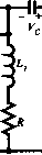 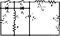 (a) (b) figure 17.41 Four-quadrant operating Luo-converter. (a) Circuit 1; and (b) circuit 2. 1. Mode A (Quadrant I): Electrical energy is transferred from source side to load side 2. Mode В (Quadrant II): Electrical energy is transferred from load side v2 to source side У^; 3. Mode С (Quadrant III): Electrical energy is transferred from source side to load side and 4. Mode D (Quadrant IV): Electrical energy is transferred from load side - v2 to source side V. Each mode has two states: on and off. Usually, each state is operating in a different conduction duty k. The switches are the power MOSFET devices. Circuit 1 in Fig. 17.41 implements Modes A and B, and circuit 2 in Fig. 17.41 implements Modes С and D. Circuits 1 and 2 can be changed over by auxiliary switches (not shown in the figure). Mode A. During the on state switch is closed, and switch s2 and diodes D and D2 are not conducting. In this case inductor currents and ii2 increase, and z\ = + ii2-During the off state switches S, s2, and diode D are off and diode D2 is conducted. In this case current flows via diode D2 to charge capacitor C. In the meantime, current ii2 continues to flow through load battery v2- The freewheehng diode current ijj2 = h\ + hi- Mode A implements the characteristics of the buck-boost conversion. Mode B. During the on state switch s2 is closed, and switch Si and diodes and D2 are not conducting. In this case inductor current 12 increases by biased v2 and inductor current ill increases by biased Vq. Therefore, capacitor voltage Vq reduces. During the off state switches S, s2 and diode D2 are not on, and only diode is on. In this case source current = i + i2y which is a negative value to perform the regenerative operation. Inductor current ii2 flows through capacitor C, and it is charged by current ii2- After capacitor C, ii2 then flows through the source V. Inductor current in flows through the source V as well via diode D. Mode В implements the characteristics of the boost conversion. Mode C. During the on state switch Si is closed, and switch s2 and diodes and D2 are not conducting. In this case inductor currents in and ii2 increase and z\ = in. During the off state switches Si, s2 and diode are off and diode D2 is conducting. In this case current in flows via diode D2 to charge capacitor С and the load battery v2 via inductor L2. The freewheehng diode current ii)2 = hi = + h- Mode С implements the characteristics of the buck-boost conversion. Mode D. During the on state switch s2 is closed, and switch Si and diodes and D2 are not conducting. In this case inductor current in increases by biased v2 and inductor current ii2 decreases by biased (v2 - c)- Therefore, capacitor voltage Vq reduces. Current in = c-on + h- During the off state switches Si, s2 and diode D2 are not on, and only diode Dl is on. In this case source current z\ = in, which is a TABLE 17.1 Switch status (blank space means OFF) Switch Mode A (Ql) Mode В (Qll) Mode С (QUI) Mode D (QIV) or Diode---- State- State- State- State- State- State- State- State-on off on off on off on off Circuit Circuit 1 ON S2 ON D, ON Circuit 2 ON negative value to perform the regenerative operation. Inductor current /2 flows through capacitor С that is charged by current 2, that is, ic-off = h- Mode D implements the characteristics of the boost conversion. Summary. The switch status is shown in Table 17.1. Operation of modes A, B, C, and D is the same as in the description in Sections 17.5.1 and 17.5.2. 17.6 Switched-Capacitor Multiquadrant Luo-Converters Switched-component converters are third-generation converters, and they are made only of inductors or capacitors. They usually perform in the systems between two voltage sources: Vl and v2- Voltage source Vi is positive voltage and voltage v2 is the load voltage that can be positive or negative. In the investigation both voltages are constant voltage. As Vi and v2 are constant values, the voltage-transfer gain is constant. Our research wiU concentrate on the working current and the power transfer efficiency rj. The resistance R of the capacitors and inductors has to be considered for the power transfer efficiency rj calculation. From a review of the literature, we found that almost all of the papers investigated switched-component converters working in single-quadrant operation. Luo and his colleagues have developed this technique into multiquadrant operation, which we wiU describe here in the next sections. Switched capacitor multiquadrant Luo-converters are third-generation converters, and they are made only of capacitors. Because these converters implement voltage-lift and current-amplification techniques, they have the advantages of high power density, high-power transfer efficiency and low EMI. They have two modes: two-quadrant switched-capacitor dc/dc Luo-converter; and four-quadrant switched-capacitor dc/dc Luo-converter. The two-quadrant switched-capacitor dc/dc Luo-converter in forward operation has been derived for the energy trans- mission of a dual-voltage system in two-quadrant operation. Both source and load voltages are positive polarity. It performs in the first-quadrant Qj and the second quadrant Qn corresponding to the dc motor forward operation in motoring and regenerative braking states. The four-quadrant switched-capacitor dc/dc Luo-converter has been derived for the energy transmission of a dual-voltage system in four-quadrant operation. The source voltage is positive and load voltage can be positive or negative polarity. It performs four-quadrant operation corresponding to the dc motor forward and reverse operation in motoring and regenerative braking states. From the analysis and calculation, the conduction duty к does not affect the power transfer efficiency, but it does affect the input and output power in a smaU region. The maximum output power corresponds to к = 0.5. 17.6.1 Two-Quadrant Switched-Capacitor DC/DC Luo-Converter This converter is shown in Fig. 17.42. It consists of nine switches, seven diodes and three capacitors. The high source voltage Vjj and low load voltage are usually considered as constant voltages, for example, the source voltage is 48 V and the load voltage is 14 V. There are two modes of operation: Mode A (Quadrant I): electrical energy is transferred from the side to the Vi side; and Mode В (Quadrant II): electrical energy is transferred from the side to the Vj side. Each mode has two states: on and off. Usually, each state is operating in different conduction duty k. The switching period is T, where T = 1 , where /is the switching frequency. The switches are the power MOSFET devices. The parasitic resistance of aU switches is r. The equivalent resistance of aU capacitors is and the equivalent voltage drop of aU diodes is Vj-,. Usually, we select the three capacitors to have same capacitance С = Q = C2 = C3. Some reference data are useful: rs = 0.03 Q, Гс = 0.02 Q and V) = 0.5 V, / = 5 kHz, and С = 5000 F. The switch status is shown in Table 17.2. -H<h TABLE 17.2 Switch status (blank space means OFF)
For Mode A, the on state is shown in Fig. 17.43a: switches Si and SiQ are closed and diodes D5 and D5 are conducting. Other switches and diodes are open. In this case capacitors Q, C2 and C3 are charged via the circuit Vjj-Si-Ci-D-C2-D-C3-S10, and the voltage across capacitors Q, C2 and C3 is increasing. The equivalent circuit resistance is Rj = (2г5 + Згс) = 0.12 Q, and the voltage deduction is 2Ve) = IV. The off state is shown in Fig. 17.43b: switches S2, S3 and S4 are closed and diodes Dg, Dg and are conducting. Other switches and diodes are open. In this case capacitor Q (C2 and C3) is discharged via the circuit 52(3 and 54)--D{Dg and Diq)-Ci{C2 and C3), and the voltage across capacitor Q (C2 and C3) is decreasing. Mode A implements the current-amplification technique. The voltage and current waveforms are shown in Fig. 17.43c. All three capacitors are charged in series during the on state. The input current flows through three capacitors and the charges accumulated on the three capacitors should be the same. These three capacitors are discharged in paraUel the off state. Therefore, the output current is amplified by three times. The variation of the voltage across capacitor Q is: Avci = к{Ун - Vci = 2V ) 2Лк(1 - k)(Vjj - ЗУ, - 5V ) (2.4 + 0.6k)fCR After calculation. к{Ун - 2Vp) + 2.4(1 - k)iVi + Vp) 2.4 + 0.6fc The average output current is ici(t)dt 3(1 - к) Vci -Vl-Vd The average input current is FIGURE 17.42 Two-quadrant switched-capacitor dc/dc Luo-converter. кТ ici(t)dtk Vjj-3Vci-2V, + + 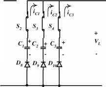 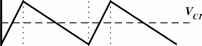 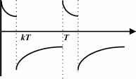 figure 17.43 Mode A operation: (a) on state; (b) off state; and (c) voltage and current waveforms. Therefore, we have 34r = 4. The output power is Po = Vik = 3(1 - k)V, The input power is af P -V I -kV я-ЗУа-Ур The transfer efficiency is I-k3V,Vc-V-VR к Vh VH-3Vr,-VnR For Mode B, the on state is shown in Fig. 17.44a: switches Sg, S9 and SiQ are closed and diodes D2, D3 and D4 are conducting. Other switches and diodes are off. In this case aU three capacitors are charged via each circuit yj-D2(and D3, D4)-Ci(and C2, C3)-S8(and S9, S), and the voltage across three capacitors are increasing. The equivalent circuit resistance is Rbn = + and the voltage deduction is Vj in each circuit. The off state is shown in Fig. 17.44b; switches S5, S and S7 are closed and diode D is on. Other switches and diodes are open. In this case all capacitors are discharged via the circuit Vi-Sj-C-S-C2-S-Ci-Di-Vjj, and the voltage across all capacitors is decreasing. Mode В implements the voltage-lift technique. The voltage and current waveforms are shown in Fig. 17.44c. All three capacitors are charged in parallel during the on state. The input voltage is apphed to the three capacitors symmetrically, so that the voltages across these three capacitors should be the same. They are discharged in series during the off state. Therefore, the output voltage is lifted by three times. The variation of the voltage across capacitor С is: Avci = After calculation. k(l - kMV, - Vr,) - Vh] Vci = KVl - Ув)(Ун - + Vd) The average input current г fkT ici(t)dt + il-k) 3Vci + Vl-V -Vo R-bf The average output current ic,(t)dt (1 - к) From this formula, we have 44r = h- S S Sj ,D D DOn у 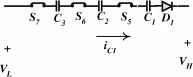
figure 17.44 Mode В operation: (a) on state; (b) off state; and (c) voltage and current waveforms. The input power Pi - The output power Po = V I = Уя(1 - к) The transfer efficiency is - - 4У, 17.6.2 Four-Quadrant Switched-Capacitor DC/DC Luo-Converter The four-quadrant switched-capacitor dc/dc Luo-converter is shown in Fig. 17.45. Because it performs the voltage-lift technique, it has a simple structure with four-quadrant operation. This converter consists of eight switches and two capacitors. The source voltage and load voltage v2 (-B- a battery or DC motor back-EMF) are usually constant voltages. Here, they are assumed to be ±21 and ±14 V. Capacitors Q and c2 are the same, and Q = c2 = 2000 F. The circuit equivalent resistance = 50 mQ. Therefore, there are four modes of operation for this converter: 1. Mode A - the energy is transferred from source to positive voltage load; the first quadrant-operation Qj; 2. Mode В - the energy is transferred from positive voltage load to source; the second quadrant-operation Qii; 3. Mode С - the energy is transferred from source to negative voltage load; the third quadrant-operation Qui; and 4. Mode D - the energy is transferred from negative voltage load to source; the fourth quadrant-operation Qiv The first quadrant (Mode A) is the so-caUed forward motoring (Forw. Mot.) operation; and v2 are positive, and and I2 are positive as weU. The second quadrant (Mode B) is the so-called forward regenerative (Forw. Reg.) braking operation; and v2 are positive, and and /2 are negative. The third quadrant (Mode C) is the so-caUed reverse motoring (Rev. Mot.) operation; and are positive, and v2 and are negative. The fourth quadrant (Mode D) is the so-called reverse regenerative (Rev. Reg.) braking operation; and /2 are positive, and and v2 are negative. 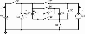 figure 17.45 Four quadrant switched capacitor dc/dc Luo-converter.
Each mode has two conditions: > and < v2 (or iv2i for Qjjj and Qiv)- Each condition has two states: on and off. Usually, each state is operating in a different conduction duty к for different currents. As usual, the efficiency of all switched-capacitor dc/dc converters is independent of the conduction duty cycle k. The switching period is T, where T = 1 . The switch status is shown in Table 17.3. As usual, the transfer efficiency rehes only on the ratio of the source and load voltages, and it is independent of R, C, f and k. We select /с = 0.5 for our description. Other values for the reference are / = 5kFLz, Y = 21V and Y = 14 V, and total С = 4000 F, R = 50 mQ. For Mode Al, condition Y > Y is shown in Fig. 17.45a. Because V > two capacitors Q and C are connected in parallel. During the switch-on state, switches S, S4, S and Sg are closed and other switches are open. In this case capacitors Cy C2 are charged via the circuit v1-s1-Q c2-S4, and the voltage across capacitors Q and c2 is increasing. During the switch-off state, switches s2, S4, S and Sg are closed and other switches are open. In this case capacitors Q c2 are discharged via the circuit s2-v2-4-Q Q and the voltage across capacitors Q and c2 is decreasing. Capacitors Q and c2 transfer the energy from the source to the load. Yc = kY+{l-k)Y2 The average current Vc-Ъ icit)dt (l-k) ic(t)dt к Ух-Ус R The transfer efficiency is Po \-kV,Vc-V, V, For Mode A2, condition Y < Y is shown in Fig. 17.45b. Because V < V25 two capacitors Q and C are connected in parallel during switch-on and in series during switch-off. This is the so-called voltage-lift technique. During the switch-on state, switches S, S4, S and Sg are closed and other switches are open. In this case capacitors c1 c2 are charged via the circuit v1-s1-Q c2-S4, and the voltage across capacitors Q and c2 is increasing. During the switch-off state, switches s2, S4 and S7 are closed and other switches are open. In this case capacitors Q and C are discharged via the circuit s2-v2-4-c1-S7-c2, and the voltage across capacitor Q and C is decreasing. Capacitors Q and C transfer the energy from the source to the load. The average capacitor voltage is Vc = =XX.l S1 1-0-Q- vcii= S2 S6 C1 S7 C2 S5 S2 -O-D- Vci -r - - C2 S5 (i) Switch-on: SI, S4, S6 & S8 on (ii) Switch-off: S2, S4, S6 & S8 on (iii) Waveforms FIGURE 17.45a Mode Al (quadrant I): forward motoring with > f2. TABLE 17.3 Switch status (none of the mentioned switches are open) The average capacitor vohage, S2 -O-D- S6 O-D- tO-D-S7 C1, S8 -O-D- S2 S6 i=vci V1 V2 V1 i,
(i) Switch-on: S2, S4, S6 & S8 on (ii) Switch -off: SI, S4(S5) & S7 on (iii) Waveforms. FIGURE 17.45b Mode A2 (quadrant I): forward motoring with < V2. The average current 2VC-V2 ic(t)dt C2-S7-C1, and the voltage across capacitors Q and C2 is decreasing. Capacitors Q and C2 transfer the energy from the load to the source. Therefore, we have I2 = 21. The average capacitor voltage is ic(t)dt Vc = 0.5v2 + Vi 2.5 = 11.2 The average current The transfer efficiency is A2 = IT = l-kV22Vr-V2 V, к V,V,- Vc 2V, 2Vc - V, ic(t)dt (l-k) For Mode Bl, condition V > V2 is shown in Fig. 17.45c. Because Vi> V2, two capacitors Q and C2 are connected in parallel during switch-on and in series during switch-off. The voltage-lift technique is applied. During the switch-on state, switches S2, S4, and Sg are closed. In this case capacitors j transfer efficienc i C1 C2 are charged via the circuit V2-S2-C1 C2-S, and the voltage across capacitors Q and C2 is increasing. During the switch-off state, switches S, S4 and S7 are closed. In this case capacitors Q and C2 are discharged via the circuit 51-1-54- ic(t)dt к l-kV2Vc-V У1 Pi к V2V2- Vc S2 -O-D- S5 C2 S7 C1 S8 -o-о ==Vci S2 S6 V1 V2 ssJJ S1 o-On ==Vci (i) Switch-on: S2, S4, S6 & S8 on (ii) Switch -off: SI, S4(S5) & S7 on
(iii) Waveforms. 1 ... 35 36 37 38 39 40 41 ... 91 |
|||||||||||||||||||||||||||||||||||||||||||||||||||||||||||||||||||||||||||||||||||||||||||||||||||||||||||||||||||||||||||||||||||||||||||||||||||||||||||||||||||||||||||||||||||||||||||||||||||||||||
|
© 2026 AutoElektrix.ru
Частичное копирование материалов разрешено при условии активной ссылки |