 |
 |
 |
| Главная Журналы Популярное Audi - почему их так назвали? Как появилась марка Bmw? Откуда появился Lexus? Достижения и устремления Mercedes-Benz Первые модели Chevrolet Электромобиль Nissan Leaf |
Главная » Журналы » Metal oxide semiconductor 1 ... 36 37 38 39 40 41 42 ... 91 S5 C2 S2 -O-D- 86 -C3-D- S7 C1 88 -o-о S5 C2 S2 S6 S7 C1 S8 -o-fy (i) Switch-on: S2, S4, S6 & S8 on (ii) Switch -off: SI, S4(S5), S6 & S8 on (iii) Waveforms. FIGURE 17.45d Mode B2 (quadrant II): forward regenerative braking with < For Mode B2, condition < v2 is shown in Fig. 17.45d. Because < two capacitors Q and c2 are connected in parallel During the switch-on state, switches 52,4, S and Sg are closed. In this case capacitors Q c2 are charged via the circuit v2~2~Q Q~4 and the voltage across capacitors Q and c2 is increasing. During the switch-off state, switches S, S4, S and Sg are closed. In this case capacitors C1 C2 are discharged via the circuit Si-Vi-S-Ci C2, and the voltage across capacitors Q and c2 is decreasing. Capacitors Q and c2 transfer the energy from the load to the source. Therefore, we have I2 = Ii- The average capacitor vohage is: Vc = kV2 + (l-k)V The average current ic(t)dt (1-k) ic(t)dt The transfer efficiency is l-kV,Vc-V, V, Пв2--;г- k v,v,-Vr For Mode CI, condition > v2i is shown in Fig. 17.45e. As > IV2I5 two capacitors Q and c2 are connected in parallel. During the switch-on state, switches S, S4, S and Sg are closed. In this case capacitors c1 c2 are charged via the circuit V-S-C C2-S, and the voltage across capacitors Q and c2 is increasing. During the switch-off state, switches S3, S5, S and Sg are closed. Capacitors Q and c2 are discharged via the circuit S,-V2-S-Cy С2У and the voltage across capacitors Q and c2 is decreasing. Capacitors Q and c2 transfer the energy from the source to the load. We have The average capacitor voltage is Ус = 1+(1-)1 v2i The average current (absolute value) is ic{t)dt{l-k) УС-\У2\ Vci== S2 S6 C1 87~7 С2 S5 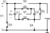 (i) Switch-on: SI, S4, S6 & S8 on (ii) Switch-off: S3, S5, S6 & S8 on (iii) Waveforms S1 r-O-Q- vcii= S2 S6 i -(j-Q-m- 1C1 S7 I 1( Vci= S2 S6 C1 S7
(i) Switch-on: SI, S4, S6 & S8 on (ii) Switch-off: S3, S5 & 5*7 on (iii) Waveforms FIGURE 17.45f Mode C2 (quadrant III): reverse motoring with < IF2I. and the average input current is The average currents = T ic(t)dt к Ух-Ус R 2Vc-\V2\ ic(t)dt (1-k) The transfer efficiency is i-ivl VC-IV2I \У2\ к У г У,-Ус For Mode С2, condition < v2i is shown in Fig. 17.45f. As < IV2I5 two capacitors Q and c2 are connected in parallel during switch-on and in series during switch-off, applying the voltage-lift technique. During the switch-on state, switches S, S4, and Sg are closed. Capacitors Q and c2 are charged via the circuit Vi-Si-Ci C2-S, and the voltage across capacitors Q and c2 is increasing. During switch-off state, switches S3, S5 and S7 are closed. Capacitors Q and c2 are discharged via the circuit S3-v2-S5-Q-S7-c2, and the voltage across capacitor Q and c2 is decreasing. Capacitors Q and c2 transfer the energy from the source to the load. We have = 2/2-The average capacitor voltage is Vr = - 0.5V, 1=11.2V ic(t)dt к Ух-Ус R The transfer efficiency is \-k\V2\2Vc-\V2\ IV2I C2 = = к V For Mode Dl, condition > iv2i is shown in Fig. 17.45g. Because V>\V2\, two capacitors Q and c2 are connected in parallel during switch-on and in series during switch-off, applying the voltage-lift technique. During the switch-on state, switches S3, S5, S and Sg are closed. In this case capacitors Q c2 are charged via the circuit v2~3~Q Q~ S5, and the voltage across capacitors Q and c2 is increasing. During the switch-off state, switches S, S4 and S7 are closed. Capacitors Q and c2 are discharged via the circuit Si-yi-S4-c2-S7-c1, and the voltage across capacitors Q and c2 is S2 S6 -O-D- S7 C1 S8 -o-о S2 S6 S5 C2 V1 V2 =F - S7 C1 ==Vci
(i) Switch-on: Si, SJ, Sd & S8 on (ii) Switch-off: 5*7, S4 8c S7 on (iii) Waveforms decreasing. Capacitors Q and c2 transfer the energy from the and load to the source. We have /2 = h-The average capacitor voltage is The average currents 2Vc - V, icit)dt (l-k) кТ -f кТ icit)dt : The transfer efficiency is l-k\V,\2Vc-\V,\ \Vj\ 2У, кТ The transfer efficiency is к \У2\\У2\-Ус 2121 For Mode D2, condition < v2i is shown in Fig. 17.45h. As < IV2I5 two capacitors Q and c2 are connected in parallel. During switch-on state, switches S3, S5, S and Sg are closed. In this case capacitors Q c2 are charged via the circuit V2-S3-c1 c2-S5, and the voltage across capacitors Q and c2 is increasing. During the switch-off state, switches S, S4, S and Sg are closed. Capacitors Q and c2 are discharged via the circuit Si-yi-S4-Q c2, and the voltage across capacitors Q and c2 is decreasing. Capacitors Q and c2 transfer the energy from the load to the source. We have I2 = Ii-The average capacitor vohage is Ус = 12!+ (1-)1 The average currents For Mode Dl, condition > iv2i is shown in Fig. 17.45g. Because > V2I5 two capacitors Q and c2 are connected in parallel during switch-on and in series during switch-off, applying the voltage-lift technique. During the switch-on state, switches S3, S5, S and Sg are closed. In this case capacitors C1 C2 are charged via the circuit v2~3~Q Q~ S5, and the voltage across capacitors Q and c2 is increasing. During the switch-off state takes S, S4 and S7 are closed. Capacitors Q and c2 are discharged via the circuit s1-V4-S4-c2-S7-c1, and the voltage across capacitors Q and c2 is decreasing. Capacitors Q and c2 transfer the energy from the load to the source. We have I2 = 21. The average capacitor vaoltage is Vr = The average currents 0.51v2i +Vi = 11.2 ic(t)dt (1-k) 2Vc - Vl R t Vr-V, ic(t)dt(l-k)- ic(t)dt к 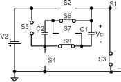 S5 C2 V1 V2 S2 S6 -O-D- S7 C1 S8 -o-о ==Vci
(i) Switch-on: S3, S5, S6 & S8 on (ii) Switch-off: SI, S4, S6 & S8 on (iii) Waveforms FIGURE 17.45h Mode d2 (quadrant IV): reverse regenerative braking with < IF2I. The transfer efficiency is l-k V, 2Vr- V, к V2lV2l-c 2IV2I For Mode D2, condition < v2i is shown in Fig. 17.45h. As 1 < 12! two capacitors Q and c2 are connected in paraUel. During switch-on state, switches S3, S5, S and Sg are closed. In this case capacitors Q c2 are charged via the circuit V2-S3-c1 c2-S5, and the voltage across capacitors Q and c2 is increasing. During the switch-off state, switches S, S4, S and Sg are closed. Capacitors Q and c2 are discharged via the circuit Si-Vi-S-Ci C2y and the voltage across capacitors Q and c2 is decreasing. Capacitors Q and c2 transfer the energy from the load to the source. We have 4 = A-The average capacitor vohage is Vc = k\V2\(l-k)V, The average capacitor currents The two-quadrant switched-inductor dc/dc Luo-converter in forward operation has been derived for the energy transmission of a dual-voltage system; both source and load voltages are positive polarity. It performs in the first-quadrant Ql and the second quadrant Qu corresponding to the dc motor forward operation in motoring and regenerative braking states. The two-quadrant switched-inductor dc/dc Luo-converter in reverse operation has been derived for the energy transmission of a dual-voltage system. The source voltage is positive and the load voltage is negative polarity. It performs in the third-quadrant Qjjj and the fourth-quadrant Qjy corresponding to the dc motor reverse operation in motoring and regenerative braking states. The four-quadrant switched-inductor dc/dc Luo-converter has been derived for the energy transmission of a dual-voltage system. The source voltage is positive and the load voltage can be positive or negative polarity. It performs four-quadrant operation corresponding to the dc motor forward and reverse operation in motoring and regenerative braking states. ic(t)dt (l-k) ic(t)dt к Ух-Ус R The transfer efficiency is D2 = = Po l-k\V2\2Vc-\V2\ \V2\ Pi к V, V,-Vc 2V, 17.7 Switched-Inductor Multiquadrant Luo-Converters Switched-capacitor converters usually have many switches and capacitors, especially for a system with a high ratio between source and load voltages. The switched inductor converter usually has only one inductor even if it works in single-, two-and/or four-quadrant operation. Simphcity is the main advantage of aU switched inductor converters. Switched inductor multiquadrant Luo-converters are third-generation converters, and they have only one inductor. These converters have been derived from chopper circuits, and they have three modes: two-quadrant switched-inductor dc/dc Luo-converter in forward operation; two-quadrant switched-inductor dc/dc Luo-converter in reverse operation; and four-quadrant switched-inductor dc/dc Luo-converter. 17.7.1 Two-Quadrant Switched-Inductor DC/DC Luo-Converter in Forward Operation The F 2Q SI Luo-converter shown in Fig. 17.46 has two switches with two passive diodes, two inductors and one capacitor. The source voltage (У^) and load voltage (v2) are usually considered as constant voltages. The load can be a battery or motor back-electromotive force (EMF). For example, the source voltage is 42 V and load voltage is +14 V. There are two modes of operation: 1. Mode A (Quadrant I) - electrical energy is transferred from source side to load side V2; and 2. Mode В (Quadrant II) - electrical energy is transferred from load side v2 to source side V. Mode A. The equivalent circuits during switch-on and switch-off periods are shown in Fig. 17.47a,b. The typical high high -AW- FIGURE 17.46 Switched inductor quadrant I and II dc/dc Luo-converter. -*high L1 R1 -vw-  FIGURE 17.47 Mode A of F 2Q SI Luo-converter: (a) on state-Sl on; (b) off state-Sl off; and (c) input and output current waveforms. output voltage and current waveforms are shown in Fig. 17.47c. The average inductor current is The average inductor current 4 in the discontinuous region is kV, - V, v2 + Rl fL The power transfer efficiency The variation ratio of the inductor current is Ml/2 k(l-k)V R A-dis - n ~ Po V, 4 = with The power transfer efficiency Pj V2 + RIl V. R Pj- kV, The boundary between continuous and discontinuous regions is defined: С Ь that is, k(l-k)V R kV - V2 2/1 > 1 V. R k< + k(l-k) Mode B. The equivalent circuits during switch-on and switch-off periods are shown in Fig. 17.48a,b. The typical output voltage and current waveforms are shown in Fig. 17.48c. The average inductor current 4 is у2 - (1 - k)V R The variation ratio of the inductor current ii is Ai/2 k(l -k)V R V,-{l-k)V,2fL high R1 L1 FIGURE 17.48 Mode В of F 2Q SI Luo-converter: (a) on state-S2 on; (b) off state-Dl on, S2 off; and (c) input and output current waveforms. The power transfer efficiency (1 - k)V, The boundary between continuous and discontinuous regions is defined: С > 1 that is >1 or k<(l-Y]+4l-k) high high figure 17.49 Switched inductor quadrant III and IV dc/dc Luo-The average inductor current I, in the discontinuous region is converter. V1-V2 + Rh 2fL The power transfer efficiency Po V2 - RIl iB-dis - T> ~ with k<{l-)+k(l-k) Mode C. The equivalent circuits during switch-on and switch-off periods are shown in Fig. 17.50a,b. The typical output voltage and current waveforms are shown in Fig. 17.50c. The average inductor current I, is kV-(l-k)V2 R The variation ratio of the inductor current i, is 17.7.2 Two-Quadrant Switched-Inductor DC/DC Luo-Converter in Reverse Operation The R 2Q SI Luo-converter shown in Fig. 17.49 consists of The power transfer efficiency two switches with two passive diodes, two inductors and one capacitor. The source voltage (У^) and load voltage (v2) are usually considered as constant voltages. The load can be a battery or motor back-electromotive force (EMF). For example, the source voltage is 42 V and load voltage is -14 V. There are two modes of operation: Aijl k(l - k)(V, + V2) R kV - (1 - k)V2 2/L Po (1 - k)V, The boundary between continuous and discontinuous regions is defined: 1. Mode С (Quadrant III): electrical energy is transferred from source side to load side - v2; 2. Mode D (Quadrant IV): electrical energy is transferred ( Xi + 2) R from load side - v2 to source side V. kV - (1 - k)V2 2/L + k{\ - k) R IfL hlgh kT T (a) (b) (c) figure 17.50 Mode С of F 2Q SI Luo-converter: (a) on state-on; (b) off state-Z)2 on, Si off; (c) input and output current waveforms. V+RI 2/1 The power transfer efficienqr C-dis - IT ~ V, V, - RI, Pi Vl v2 + RIl V, + V, V2-RIL 2 0 V,+RI, 2/1 The power transfer efficiency 4d-dis - r> - Pj VV+RI, with with k<- v, + v, k<- Vl + V2 Moc/e D. The equivalent circuits during switch-on and switch-off periods are shown in Fig. 17.51a,b. typical output voltage and current waveforms are shown in Fig. 17.51c. The average inductor current 4 is kV,-(l-k)V, R The variation ratio of the inductor current ii is MJ2 k(l - k)(V, + V2) R Il kV2-(l-k)V 2fL The power transfer efficiency Po (1 - k)V, The boundary between continuous and discontinuous regions is defined: С 1 k(l - k)(V, + V2) R kV2-(l - k)V 2fL > 1 or k< + V, + k(l - k) R 2fL 17.7.3 Four-Quadrant Switched-lnductor DC/DC Luo-Converter Switched inductor dc/dc converters successfully overcome the disadvantage of switched-capacitor converters. Usually, only one inductor is required for each converter with 1- or 2- or 4-quadrant operation no matter how large the difference of the input and output voltages. Therefore, the switched inductor converter has a very simple topology and circuit. Consequently, it has high power density. Fiere a switched inductor four-quadrant dc/dc Luo-converter is introduced. This converter is shown in Fig. 17.52 and it consists of three switches, two diodes and only one inductor L. The source voltage Vl and load voltage v2 (-B- battery or dc motor back-EMF) are usually constant voltages; R is the equivalent resistance of the circuit, and it is usually small; > v21 and are assumed to +42 and ibl4V, respectively. Therefore, there are four quadrants (modes) of operation: 1. Mode A - the energy is transferred from source to positive voltage load; the first quadrant-operation Qj; 2. Mode В - the energy is transferred from positive voltage load to source; the second quadrant-operation Qii; high *low low кТ T I2 кТ T (a) (b) (c) FIGURE 17.51 Mode D of F 2Q SI Luo-converter. (a) on state-52 on; (b) off state-D on, S2 off; (c) input and output current waveforms. The average inductor current 4 in the discontinuous region is The average inductor current in the discontinuous region is 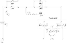 FIGURE 17.52 Four-quadrant switched inductor dc/dc Luo-converter. 3. Mode С - the energy is transferred from source to negative voltage load; the third quadrant-operation Qui; 4. Mode С - the energy is transferred from negative voltage load to source; the fourth quadrant-operation Qiv; The first quadrant is the so-called forward motoring (Forw. Mot.) operation; and v2 positive, and and I2 are positive as weU. The second quadrant is the so-called forward regenerative (Forw. Reg.) braking operation; and V2 are positive, and and I2 are negative. The third quadrant is the so-caUed reverse motoring (Rev. Mot.) operation; and are positive, and V2 and I2 are negative. The fourth quadrant is the so-caUed reverse regenerative (Rev. Reg.) braking operation; Vl and I2 are positive, and and v2 negative. Each mode has two states: on and off. Usually, each state is operating in a different conduction duty k. The switching period is T where T = 1 . The switch status is shown in Table 17.4. Mode A is shown in Fig. 17.47. During the switch-on state, switch Si is closed. In this case the source voltage Vi supplies the load v2 inductor L, and inductor current i, increases. During the switch-off state, diode D2 is on. In this case current i, flows through the load v2 the freewheehng diode d2, and it decreases. Mode В is shown in Fig. 17.48. During the switch-on state, switch s2 is closed. In this case the load voltage v2 supplies the TABLE 17.4 Switch status (none of the mentioned switches are off)
inductor L, and inductor current i, increases. During the switch-off state, diode is on, and current i, flows through the source Vi and load v2 the diode D, and it decreases. Mode С is shown in Fig. 17.50. During the switch-on state, switch Si is closed. The source vohage Vi supphes the inductor L, and inductor current i, increases. During the switch-off state, diode D2 is on. Current i, flows through the load v2 the freewheeling diode d2, and it decreases. Mode D is shown in Fig. 17.51. During the switch-on state, switch s2 is closed. The load voltage v2 supphes the inductor L, and inductor current i, increases. During the switch-off state, diode is on. Current i, flows through the source Vi via the diode D, and it decreases. All descriptions of the Modes A, B, C, and D are the same as in Sections 17.7.1 and 17.7.2. 17.8 Multiquadrant ZCS Quasi-Resonant Luo-Converters Soft-switching converters are fourth-generation converters, consisting only of an inductor or capacitors. They usually perform in the systems between two voltage sources - Vi and V2. Voltage source Vi is positive voltage and voltage v2 is the load voltage that can be positive or negative. In this study, both voltages are constant voltages. As Vi and v2 re constant values, the voltage-transfer gain is constant. Our research wiU concentrate on the working current and the power transfer efficiency f]. The resistance R of the inductor has to be considered for the power transfer efficiency f] calculation. From a review of the literature, we found that almost aU the papers investigated switched-component converters working in the single-quadrant operation. Luo and his coUeagues have developed this technique into the multiquadrant operation, which wiU be described in what follows. Multiquadrant ZCS quasi-resonant Luo-converters are fourth-generation converters. Because these converters implement the zero-current-switching technique, they have the advantages of high power density, high-power transfer efficiency, low EMI, and reasonable EMC. They have three modes: two-quadrant ZCS quasi-resonant dc/dc Luo-converter in forward operation; two-quadrant ZCS quasi-resonant dc/dc Luo-converter in reverse operation; and four-quadrant ZCS quasi-resonant dc/dc Luo-converter. The two-quadrant ZCS quasi-resonant dc/dc Luo-converter in forward operation is for the energy transmission of a dual-voltage system. Both source and load voltages are positive polarity. It performs in the first-quadrant Qj and the second-quadrant Qii corresponding to the dc motor forward operation in motoring and regenerative braking states. The two-quadrant ZCS quasi-resonant dc/dc Luo-converter in reverse operation is also for the energy transmission of a dual-voltage system, but in this case the source voltage is positive and the load voltage is negative polarity. It performs in the third-quadrant Qm and the fourth-quadrant Qjy corresponding to the dc motor reverse operation in motoring and regenerative braking states. The four-quadrant ZCS quasi-resonant dc/dc Luo-converter is for the energy transmission of a dual-voltage system. The source voltage is positive, and load voltage can be positive or negative polarity. It performs four-quadrant operation corresponding to the dc motor forward and reverse operation in motoring and regenerative braking states. 17.8.1 Two-Quadrant ZCS Quasi-Resonant Luo-Converter in Forward Operation As both voltages are low, this converter is designed as a zero-current-switching quasi-resonant converter (ZCS-QRC). It is shown in Fig. 17.53. This converter consists of one main inductor L and two switches with their auxiliary components. Assuming that the main inductance is sufficiently large, the current il is constant. The source voltage and load voltage v2 are usually constant = 42 V and v2 = lV. There are two modes of operation: 1. Mode A (Quadrant I) - electrical energy is transferred from Vl side to v2 side; and 2. Mode В (Quadrant II) - electrical energy is transferred from v2 side to V side. Each mode has two states: on and off. The switch status of each state is shown in Table 17.5. Mode A is a ZCS buck converter. The equivalent circuit, current and voltage waveforms are shown in Fig. 17.54. There are four time regions for the switching-on and switching-off 1 СФ figure 17.53 Two-quadrant (gi + gn) dc/dc ZCS quasi-resonant Luo-converter. table 17.5 Switch status (the blank space means off)
period. The conduction duty cycle is /с = (t + 2) when the input current flows through the switch and inductor L. The whole period is T = (t + 2 + % + 4). Some formulas are listed in the following: CO, =- Zx=b and , ,. = /,+l and a. = sm 2 =-(я + a) and io = + sa) tA = - and = 4+- Zi 7i/2 + cci V] cosai , Zi 7i/2 + T= ti + t2 + t3 + t4 and f=l/T Mode В is a ZCS boost converter. The equivalent circuit, current and voltage waveforms are shown in Fig. 17.55. There are four time regions for the switching-on and switching-off period. The conduction duty cycle is к = (t + 2), but the output current flows only through the source V in the period 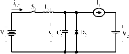
figure 17.54 Mode A operation: (a) equivalent circuit; (b) waveforms. 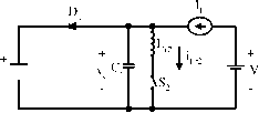 V, т=
FIGURE 17.55 Mode В operation: (а) equivalent circuit; (b) waveforms. t. The whole period is T = (t + 2 + % + 4). Some formulas are listed in what foUows: = - 2 = д/ and i2-peak = h- and (X2 = sin tj- - (71 + 2) and Vrn = - 1 cos a, {V, - Vco)C, kV, и и =--- and --- = - lr or h Vl T Vl T tl + t2 + % + t4 tl = tl + t2 + % T= ti + t2 + t3 + t4 and /=1/Т 17.8.2 Two-Quadrant ZCS Quasi-Resonant Luo-Converter in Reverse Operation The two-quadrant ZCS quasi-resonant Luo-converter in reverse operation is shown in Fig. 17.56. It is a new soft switching technique with two-quadrant operation, which effectively reduces the power losses and largely increases the power transfer efficiency. It consists of one main inductor L R L Luo, H. Ye and M. H. Rashid S, L, 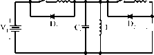 FIGURE 17.56 Two-quadrant (QIII+IV) dc/dc ZCS quasi-resonant Luo-converter. and two switches with their auxiliary components. Assuming that the main inductance L is sufficiently large, the current i, is constant. The source voltage Vi and load voltage v2 usually constant, for example, Vi = 42 V and v2 = ~28 V. There are two modes of operation: 1. Mode С (Quadrant III) - electrical energy is transferred from Vl side to - v2 side; and 2. Mode D (Quadrant IV) - electrical energy is transferred from - v2 side to Vi side. Each mode has two states: on and off . The switch status of each state is shown in Table 17.6. Mode С is a ZCS buck-boost converter. The equivalent circuit, current and voltage waveforms are shown in Fig. 17.57. There are four time regions for the switching-on and switch-ing-off period. The conduction duty cycle is kT = (ti + 2) when the input current flows through the switch Si and the main inductor L. The whole period is T = (ti + 2 + % + t). Some formulas are hsted in what foUows: CO, = \, and (Xl = sin Vi + v2 1 Ш in + 1) and Vco = (Vl - V2) + Vl sm(n/2 + Vi(l+cosai)- v2 (усо + 2)Q Vi(l+cosai)Q t2 / yj2cosa)l\ V-l(ti + t2)fVi 2cosai V2IL V Zi n/2 + 1 TABLE 17.6 Switch status (the blank space means off)
1 ... 36 37 38 39 40 41 42 ... 91 |
|||||||||||||||||||||||||||||||||||||||||||||||||||||||||||||||||||||||||||||||||||||||||||||||||||||||||||||||||||||||||||||||||||||||||||||||||||||||||||||||||||||||||||||||||||||||||||||||||||||||||||||||||||||||||||||||||||||||||||||||||||||||||||||||||||
|
© 2026 AutoElektrix.ru
Частичное копирование материалов разрешено при условии активной ссылки |