 |
 |
 |
| Главная Журналы Популярное Audi - почему их так назвали? Как появилась марка Bmw? Откуда появился Lexus? Достижения и устремления Mercedes-Benz Первые модели Chevrolet Электромобиль Nissan Leaf |
Главная » Журналы » Metal oxide semiconductor 1 ... 37 38 39 40 41 42 43 ... 91 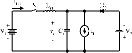 Mode D is a cross ZCS buck-boost converter. The equivalent circuit, current and voltage waveforms are shown in Fig. 17.58. There are four time regions for the switching-on and switching-off period. The conduction duty cycle is кТ = (t + 2), but the output current flows only through the source in the period t. The whole period is T = (t + 2 + 3 + t). Some formulas are listed as follows: v,-v, 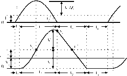 FIGURE 17.57 Mode С operation: (a) equivalent circuit; (b) waveforms. Ух + Уг 1 A -if and 2 = sm / 2 = - (71 + aj) and Vrn {У\ - У2) - У2 sin(7r/2 + v.) = У1 - ¥2(1 + cosa2) {y-Vco)Cr V2(l+cosa2)Q Y and У2(.Ч + Ч) (jy2 2cosa2 Ухк Z2 7Г/2 + 2 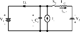 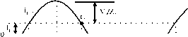
17.8.3 Four-Quadrant ZCS Quasi-Resonant Luo-Converter The four-quadrant ZCS quasi-resonant Luo-converter is shown in Fig. 17.59. Circuit 1 implements the operation in quadrants I and II, Circuit 2 implements the operation in quadrants III and IV. Circuit 1 and Circuit 2 can be converted to each other by an auxiliary switch. Each circuit consists of one main inductor L and two switches. Assuming that the main inductance L is sufficiently large, the current ii remains constant. The source and load voltages are usually constant. ab cd ab cd FIGURE 17.58 Mode D operation: (a) equivalent circuit; (b) wave- FIGURE 17.59 Four-quadrant dc/dc ZCS quasi-resonant Luo-forms. converter. for example, = 42 V and v2 = ±28 V [7-9]. There are four modes of operation: 1. Mode A (Quadrant I) - electrical energy is transferred from the side to the v2 side; 2. Mode В (Quadrant II) - electrical energy is transferred from the v2 side to the side. 3. Mode С (Quadrant III) - electrical energy is transferred from the side to the - v2 side; and 4. Mode D (Quadrant IV)-electrical energy is transferred from the - v2 side to the side. Each mode has two states - on and off. The switch status of each state is shown in Table 17.7. The operation of Mode A, B, C, and D is the same as that in the previous Sections 17.8.1 and 17.8.2. 17.9 Multiquadrant ZVS Quasi-Resonant Luo-Converters Multiquadrant ZVS quasi-resonant Luo-converters are fourth-generation converters. Because these converters implement the zero-current-switching technique, they have the advantages of high power density, high-power transfer efficiency, low EMI, and reasonable EMC. They have three modes: two-quadrant ZVS quasi-resonant dc/dc Luo-converter in forward operation; two-quadrant ZVS quasi-resonant dc/dc Luo-converter in reverse operation; and four-quadrant ZVS quasi-resonant dc/dc Luo-converter. The two-quadrant ZVS quasi-resonant dc/dc Luo-converter in forward operation is derived for the energy transmission of a dual-voltage system. Both source and load voltages are positive polarity. It performs in the first quadrant Qi and the second quadrant Qn corresponding to the dc motor forward operation in motoring and regenerative braking states. The two-quadrant ZVS quasi-resonant dc/dc Luo-converter in reverse operation is derived for the energy transmission of a dual-vohage system. The source voltage is positive polarity and the load voltage is negative polarity. It performs in the third quadrant Qm and the fourth quadrant Qjy corresponding to the dc motor reverse operation in motoring and regenerative braking states. The four-quadrant ZVS quasi-resonant dc/dc Luo-converter is derived for the energy transmission of a dual-voltage system. The source voltage is positive polarity, and load voltage can be either positive or negative polarity. It performs four-quadrant operation corresponding to the dc motor forward and reverse operation in motoring and regenerative braking states. 17.9.1 Two-Quadrant ZVS-Quasi-Resonant DC/DC Luo-Converter in Forward Operation The two-quadrant ZVS quasi-resonant Luo-converter in forward operation is shown in Fig. 17.60. It consists of one main inductor L and two switches with their auxiliary components. Assuming the main inductance L is sufficiently large, the current il is constant. The source voltage and load voltage v2 are usually constant, for example, = 42 V and V2 = 14 V. There are two modes of operation: 1. Mode A (Quadrant I) - electrical energy is transferred from the side to the v2 side; and 2. Mode В (Quadrant II) - electrical energy is transferred from the v2 side to the side. Each mode has two states - on and off. The switch status of each state is shown in Table 17.8. Mode A is a ZVS buck-converter shown in Fig. 17.61. There are four time-regions for the switching-on and switching-off period. The conduction duty cycle is /сТ = (% + t) when the input current flows through the switch Si and the main FIGURE 17.60 Two-quadrant (QI+QII) dc/dc ZVS quasi-resonant Luo-converter. TABLE 17.7 Switch status (the blank space means off)
17 DC/DC Conversion Technique and Nine Series LUO-Converters table 17.8 Switch status (the blank space means off)
<5>- 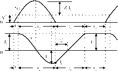 figure 17.61 Mode A operation: (a) equivalent circuit; (b) waveforms. inductor L The whole period is T = (t + 2 + % + t). Some relevant formulas are listed in the following: 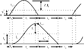 figure 17.62 Mode В operation: (a) equivalent circuit; (b) waveforms. Mode В is a ZVS boost converter shown in Fig. 17.62. There are four time regions for the switching-on and switching-off period. The conduction duty cycle is кТ = (% + t), but the output current flows only through the source in the period (tl + 2). The whole period is T = (t + 2 + % + t). Some relevant formulas are listed in the following: 9 - 2 = д/ and Vc2-peak = П + ih CD. = 1 = and v,i p,j, = + 2 I and oc,=sm- tj = -(71 + a,) and i Q, = -I, cos a. n=- and a,=sm t2= - (я + CC2) and iQ2 = 4(1 + cos CC2) t. = (h - hoi)Lr Ух 4V2 1 Vl ~ T tA = tl + ?2 + % + t4 =Ьф and 7i = IlV2 1 1 1 T V, T u + t. V2 1 г = tl + ?2 + t3 + 4 and / = l/T switch Si and the main inductor L. The whole period is T = (tj + 2 + % + t). Some formulas are listed as follows: k = - T = tl + t2 + t3 + t4 and / = 1/T 17.9.2 Two-Quadrant ZVS Quasi-Resonant DC/DC Luo-Converter in Reverse Operation The two-quadrant ZVS quasi-resonant Luo-converter in reverse operation is shown in Fig. 17.63. It consists of one main inductor L and two switches with their auxiliary components. Assuming the main inductance L is sufficiently large, the current i, is constant. The source voltage Vi and load voltage v2 usually constant, for example, Vi = +42 V and v2 = ~28 V. There are two modes of operation: 1. Mode С (Quadrant III) - electrical energy is transferred from the Vi side to the - v2 side; and 2. Mode D (Quadrant IV)-electrical energy is transferred from the - v2 side to the Vi side. Each mode has two states: on and off. The switch status of each state is shown in Table 17.9. Mode С is a ZVS buck-boost converter as shown in Fig. 17.64. There are four time regions for the switching-on and switching-off period. The conduction duty cycle is kT = when the input current flows through the v2 m-Y. FIGURE 17.63 Two-quadrant (QIII+IV) dc/dc ZVS quasi-resonant Luo-converter. TABLE 17.9 Switch status (the blank space means off)
CD, = ti = Zi=J- and t,i-peafc= l + 2+l4 (Vi + V2)C,i . iVi +v2 - and ai = sm t2 = -(я + ai) and ioi = ~h sin(/2 + ai) Vl T h + h + h -1 and /9 = - k = - ti + t2 + t, + и Mode D is a cross ZVS buck-boost converter as shown in Fig. 17.65. There are four time regions for the switching-on and switching-off period. The conduction duty cycle is kT = V,+V 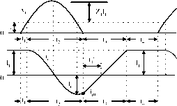 FIGURE 17.64 Mode С operation: (a) equivalent circuit; (b) waveforms. 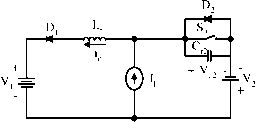 v,+v 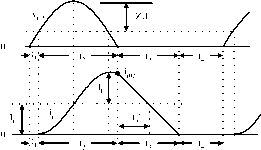 figure 17.65 Mode D operation: (a) equivalent circuit; (b) Wave forms. 17.9.3 Four-Quadrant ZVS Quasi-Resonant DC/DC Luo-Converter The four-quadrant ZVS quasi-resonant Luo-converter is shown in Fig. 17.66. Circuit 1 implements the operation in quadrants I and II, and Circuit 2 implements the operation in quadrants III and IV. Circuit 1 and Circuit 2 can be converted to each other by an auxiliary switch. Each circuit consists of one main inductor L and two switches. Assuming that the main inductance L is sufficiently large, the current ii is constant. The source and load vohages are usually constant, for example, = 42 V and V2 = ±28 V. There are four modes of operation: Mode A (Quadrant I) - electrical energy is transferred from the side to the V2 side; Mode В (Quadrant II) - electrical energy is transferred from the V2 side to the side; Mode С (Quadrant III) - electrical energy is transferred from the side to the - V2 side; and Mode D (Quadrant IV) - electrical energy is transferred from the - V2 side to the side. Each mode has two states, that is, on and off. The switch status of each state is shown in Table 17.10. The description of Modes A, B, С and D is same to that in the previous Sections 17.9.1 and 17.9.2. (% + 4), but the output current flows only through the source Vl in the period (1 + 2). The whole period is T = (1 + 2 + 3 + 4). Some formulas are listed as follows: 02== 2=,Ы- and tC2-peafc = l + 2+24 VrQ2 Vr2 t, = --, and a2 = sm h= - + 2) and iQ2 = + sin(/2 + (X2)] V1 + V2 T irdtUh(t2 + h)] = -I, and II = -zz V2 1 , , 2 + % Vl 1 tl 4= (2 + %)- t3 + t4 1 + 2 + % + к T = tl + t2 + % + t4 and / = l/T 17.10 Synchronous Rectifier DC/DC Luo-Converters Synchronous rectifier dc/dc converters are called the fifth-generation converters. The development of microelectronics and computer science requires power supphes with low output voltage and strong current. Traditional diode bridge rectifiers are not available that meet this requirement. The soft-switching technique can be applied in synchronous rectifier dc/dc converters. We have created few converters with very low C2± -I- / cd I ab cd figure 17.66 Four-quadrant dc/dc ZVS quasi-resonant Luo-converter. TABLE 17.10 Switch status (the blank space means off)
voltage (5, 3.3, and 1.8 ~ 1.5 V) and strong current (30, 60, up The intervals are: to 200 A) and high-power transfer efficiency (86, 90, up to 93%). This section introduces a few new circuits that are different from the ordinary synchronous rectifier dc/dc converters: 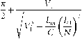 flat transformer synchronous rectifier dc/dc Luo-converter; double current synchronous rectifier dc/dc Luo-conver- . j- т . / . . Average output voltage Vo input current is L ter with active clamp circuit; zero-current-switching synchronous rectifier dc/dc Luo-converter; and zero-voltage-switching synchronous rectifier dc/dc Luo-converter. are: and /1 = The power transfer efficiency: 17.10.1. Flat Transformer Synchronous Rectifier DC/DC Luo-Converter A flat transformer SR dc/dc Luo-converter is shown in Fig. 17.67. The switches S, s2 and S3 are the low-resistance MOSFET devices with very low resistance (7-8 mQ). Because we use a flat transformer, the leakage inductance and resistance R, are smaU. Other parameters are С = 1 F, L = 1 nH, Rl = 2 mQ, L = 5 H, and Cq = 10 The input voltage is = 30 V dc, the output voltage is the output current is Iq. The transformer turns ratio is N = 12:1. The repeating period is T = l/f and conduction duty is k. There are four working modes: CD = The natural resonant frequency is и kT Rl + Rs + kVJN When we set the frequency / = 150-200 kHz, we obtained v2 = 1.8v, n = 12, Iq = 0-30A, Volume = 2.5 (in). The average power-transfer efficiency is 92.3%, and the maximum power density (PD) is 21.6VV/in 17.10.2 Double Current Synchronous Rectifier DC/DC Luo-Converter with Active Clamp Circuit The converter in Fig. 17.67 prefers a half-wave rectifier. The dc SR dc/dc Luo-converter with an active clamp circuit is shown in Fig. 17.68. The switches s1-s4 are the low-resistance MOSFET devices with very low resistance R (7-8 mQ). As S3 and s4 plus Li and l2 form a double-current circuit and s2 plus С is the active clamp circuit, this converter prefers a fuU-wave rectifier and obtains strong output current. Other parameters are С = 1 F, L = 1 nH, R, = 2 mQ, L = 5 H, and Cq = 10 F. The input voltage is = 30 V dc, output voltage is v2 the output current is Iq. The transformer turns ratio L R, N : 1 PWM ,t-k Г1Л JpJ FIGURE 17.67 Flat transformer SR Luo-converter. --Vi PWM П П FIGURE 17.68 Double-current SR Luo-converter. is N = 12 :1. The repeating period is T = 1 and conduction duty is k. There are four working modes: When we set the frequency / = 200-250 kFLz, we obtained v2 = 1.8V, N = 12, Iq = 0-35A, Volume = 2.5 (in). The average power-transfer efficiency is 94% and the maximum power density (PD) is 25W/in 17.10.3 Zero-Current-Switching Synchronous Rectifier DC/DC Luo-Converter Because the power loss across the main switch is high in dc SR dc/dc Luo-converter, we designed the ZCS SR dc/dc Luo-converter shown in Fig. 17.69. This converter is based on the dc SR dc/dc Luo-converter plus the zero-current-switching technique. It employs a double-core flat transformer: The ZCS resonant frequency is normahzed impedance is I,Lr 1 . . yi(l + cosa)Q h=-(71 +a) % = CO = The natural resonant frequency is l-k The intervals are: (Vl cos a \ The interval of tj is Average output voltage V2 and input current are: In and L = k - The power transfer efficiency: Rl + Rs + kVJN Average output voltage v2 and input current I are: The power transfer efficiency: RlRs kVJN When we set = 60 V and frequency / = 200-250 kFLz, and obtained v2 = 1-8 V, n = 12, Iq = 0-60 A, Volume = 4 (in). The average power transfer efficiency is 94.5% and the maximum power density (PD) is 27W/in. 17.10.4 Zero-Vokage-Switching Synchronous Rectifier DC/DC Luo-Converter The ZVS SR dc/dc Luo-converter is shown in Fig. 17.70. This converter is based on the dc SR dc/dc Luo-converter plus the S4 -D4 -I Li --D6 CoJ FIGURE 17.69 The ZCS dc SR Luo-converter. 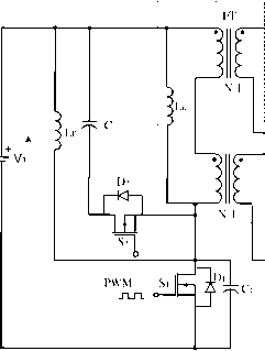 -I Li IL l2 FIGURE 17.70 ZVS dc SR Luo-converter. zero-voltage-switching technique. It employs a double-core flat transformer: (Dr = The ZVS resonant frequency is Zr = hi- and a = sin  FIGURE 17.71 Luo-resonator. normalized impedance is ViQ 1 /i(l + cosa)L The intervals are: tl + ?2 + % Average output voltage v2 and input current are: The power transfer efficiency: kVJN When we set V = 60 V and frequency / = 200-250 kFiz, we obtained v2 = 1-8 V, N = 12, Iq = 0-60 A, Volume = 4 (in). The average power-transfer efficiency is 94.5% and the maximum power density (PD) is 27W/in. 17.11 Gate Control, Luo-Resonator The Luo-resonator is shown in Fig. 17.71. It generates the PWM pulse train to drive the static switch S. The Luo-resonator is a high-efficiency and simple structured circuit with easily adjusting frequency / and conduction duty k. It consists of three operational amplifiers (OA) namely, OAl-3, and an auxiliary. These three 741-type OAs are integrated in a chip TL074 (which contains four OAs). Two potentiometers are applied to adjust the frequency / and conduction duty k. The voltage waveforms are shown in Fig. 17.72. The type-741 OA can work at a power supply of ib3-ibl8 V denoted by V+, G and V- with V - = V+. The OA2 in Fig. 17.71 acts as the integration operation, its output is a triangle waveform with regulated frequency f = l/T 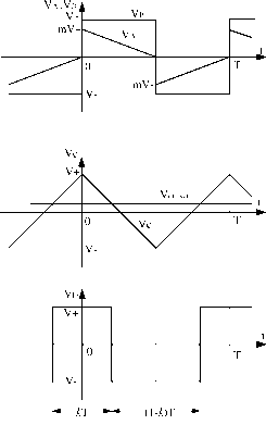 FIGURE 17.72 Voltage waveforms of Luo-resonator. controlled by potentiometer R. The OAl acts as a resonant operation, its output is a square waveform with the frequency /. The OA3 acts as a comparator, and its output V] is a square-waveform pulse train with regulated conduction duty к controlled by R. First, assume that the voltage Vg = V+ at t = 0 and feeds positively back to OAl via R2. This causes the OAl output voltage to be maintained at = V+. In the meantime, inputs to OA2 via R, and the output voltage Vq of OA2 therefore decreases towards V- with the slope l/RC. Voltage V(j feeds negatively back to OAl via R. Voltage at point A changes from (mV+) to 0 in the period of ImRC. Usually, R is set slightly smaller than R2, and the ratio is defined as m = R/R2 Thus, voltage tends towards negative. It causes the OAl output vohage Vg = V- at t = ImRC and vohage Уд jumps to mV-. Conversely, the voltage = V- at t = ImRC and feeds positively back to OAl via R2. This causes the OAl output voltage to be maintained at = V-. In the meantime, Vg inputs to OA2 via R, the output voltage Vq of OA2 therefore increases towards У+ with the slope l/RC. Voltage feeds negatively back to OAl via R. Voltage Уд at point A changes from (mV-) to 0 in the period of ImRC. Thus, voltage tends towards positive. It causes the OAl output voltage Vg = V+ at t = AmRC and voltage Уд jumps to тУ+. Voltage Vq inputs to OA3 and compares with shift signal У off-set regulated by the potentiometer Rj via R. When У off-set - 0 OA3 yields its output voltage Vj as a pulse train with conduction duty к = 0.5. Positive Vff shifts the zero cross point of voltage Vq downwards. Hence, OA3 yields its output voltage Vj as a pulse train with conduction duty /c> 0.5. Conversely, negative Vjjr shifts the zero cross point of voltage Vq upwards. Hence, OA3 yields its output voltage V] as a pulse train with conduction duty /с < 0.5 as shown in Fig. 17.72. Conduction duty к is controlled by У off-set the potentiometer R. The calculation formulas are: 4mRC /с = 0.5 + -5 off-set 2R6V+ This PWM pulse train Vj is applied to the dc/dc converter switch such as a transistor, MOSFET or IGBT via a coupling circuit. A design example: A Luo-resonator was designed as shown in Fig. 17.71 with the component values of = 10 kQ; R=R = R = 100 kQ; R = R = 95 kQ; R = 510 Q-5.1 kQ; R = 20 kQ; and С = 5.1 nR The results are m = 0.95, frequency / = 10-100 kHz, and conduction duty к = 0-1.0. plus a general IC-chip TL494. It is much smaller, cheaper, and highly efficient. The circuit is shown in Fig. 17.73. The source voltage is 24-V dc, and the output voltage is usually required to be 100 ~ 1000 V dc. It is used for an insulation test bench. Output voltage Vq was calculated as Vq = R9+R -(RRR,) The wiper of the pot R can move from 3.9 kQ to 0. The corresponding output voltage changes from 98 to 1048 V. The experimental results are listed in Table 17.11. The measured data verified the advantages of this power supply. 17.12.2 MIT 42/14-V 3-kW DC/DC Converter This is a two-quadrant ZCS-QR Luo-converter that is shown in Fig. 17.74. This converter consists of one main inductor L and two switches with their auxiliary components. Assuming the main inductance is sufficiently large, the current i, is constant. The source voltage V and load voltage у2 are usually constant, that is, У^ = 42 V and у2 = 14 V. There are two modes of operation: Mode A (Quadrant I) - electrical energy is transferred from the V side to the у2 side; and Mode В (Quadrant II) - electrical energy is transferred from the у2 side to the V side. Mode A is a ZCS buck converter. The output current can be 220 A. Mode В is a ZCS boost converter. The output current can be nearly 70 A. This converter has the volume of 270 in. It can transfer the power of 3kW between two batteries of 42 and 14 V with high power density (22.85 W/in), high efficiency (93%), and low EMI and reasonable EMC. The measured data are shown in Table 17.12. 17.12 Applications The dc/dc conversion technique has been rapidly developed and has been widely applied in industrial applications and computer peripheral equipment. Three examples are listed in what foUows: 1000-V insulation test bench; MIT 42/14-V dc/dc converter; and IBM 1.8-V/200-A power supply 17.12.3 IBM 1.8-V/200-A Power Supply This is a ZCS SR dc/dc Luo-converter as shown in Fig. 17.75. This converter is based on the dc SR dc/dc Luo-converter plus the zero-current-switching (ZCS) technique. It employs a hixaploid-core flat transformer. The ZCS resonant frequency is (Or = 17Л2Л Thousand-Volt Insulation Test Bench The traditional power supply for a high-voltage insulation test is costly, the power-transfer efficiency is very low, and the size is large. A newly designed 1000-V dc power supply is built by using a positive output Luo-converter quadruple-lift circuit and normalized impedance is  a = sm 1 ... 37 38 39 40 41 42 43 ... 91 |
||||||||||||||||||||||||||||||||||||||||||||||||||||||||||||||||||||||||||||||||||||||||||||||||||||||||||||||||||||||||||||||||||||
|
© 2026 AutoElektrix.ru
Частичное копирование материалов разрешено при условии активной ссылки |