 |
 |
 |
| Главная Журналы Популярное Audi - почему их так назвали? Как появилась марка Bmw? Откуда появился Lexus? Достижения и устремления Mercedes-Benz Первые модели Chevrolet Электромобиль Nissan Leaf |
Главная » Журналы » Metal oxide semiconductor 1 ... 52 53 54 55 56 57 58 ... 91 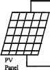 regulator Inverter unit Ш AC Load 
Battery PV Panel 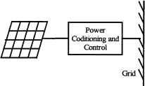 figure 23.7 (a) Stand-alone PV system; (b) PV-diesel hybrid system; (c) grid-connected PV system. - Industrial batteries - - Automoti e batteries 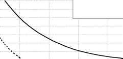 No of cycles figure 23.8 Nominal number of battery cycles vs depth-of-discharge. discharged through the PV ceUs at night when there is no sun available to generate energy. These blocking diodes also protect the battery from short circuits. In a solar power system consisting of more than one string connected in paraUel, if a short-circuit occurs in one of the strings, the blocking diode prevents the other PV strings from discharging through the short-circuited string. The battery storage in a PV system should be properly controlled to avoid catastrophic operating conditions like overcharging or frequent deep discharging. Storage batteries account for most PV system faUures and contribute significantly to both the initial and the eventual replacement costs. Charge controUers regulate the charge transfer and prevent the battery from being excessively charged and discharged. Three types of charge controUers are commonly used: Series charge regulators Shunt charge regulators Dc-dc Converters 23.2.3.1.2.1 Series Charge Regulators The basic circuit for the series regulators is given in Fig. 23.9. In the series charge controUer, the switch Si disconnects the PV generator when a predefined battery voltage is achieved. When the voltage faUs below the discharge limit, the load is disconnected from the battery to avoid deep discharge beyond the limit. The main problem associated with this type of controUer is the losses associated with the switches. This extra power loss has to come from the PV power, and this can be quite significant. Bipolar transistors, MOSFETs, or relays are used as the switches. 23.2.3.1.2 Shunt Charge Regulators In this type, as illustrated in Fig. 23.10, when the battery is fully charged the PV generator is short-circuited using an electronic switch (S). Unlike series controUers, this method works more efficiently 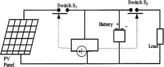 Charge Controller figure 23.9 Series charge regulator. 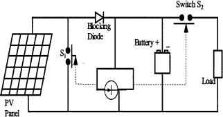 Charge Controno- figure 23.10 Shunt charge regulator. even when the battery is completely discharged, as the short-circuit switch need not be activated until the battery is fully discharged [1]. The blocking diode prevents short-circuiting of the battery. Shunt charge regulators are used for smaU PV applications (less than 20 A). Deep-discharge protection is used to protect the battery against deep discharge. When the battery voltage reaches below the minimum set point for the deep-discharge limit, switch S2 disconnects the load. Simple series and shunt regulators aUow only relatively coarse adjustment of the current flow and seldom meet the exact requirements of PV systems. 23.2.3.1.2.3 Dc-dc Converter Type Charge Regulators Switch mode dc-to-dc converters are used to match the output of a PV generator to a variable load. There are various types of dc-dc converters: Buck (step-down) converter Boost (step-up) converter Buck-boost (step-down/up) converter Figures 23.11a, 23.11b, and 23.11c show simplified diagrams of these three basic types of converters. The basic concepts are an electronic switch, an inductor to store energy, and a flywheel diode, which carries the current during that part of switching cycle when the switch is off. The dc-dc converters aUow the charge current to be reduced continuously in such a way that the resulting battery voltage is maintained at a specified value. 23,2,3,1,3 Maximum-Power-Point-Tracking (MPPT) A controUer that tracks the maximum-power-point locus of the PV array is known as an MPPT. In Fig. 23.12, the PV power output is plotted against the voltage for insolation levels from 200 W/m to 1000 W/ml The points of maximum array power form a curve termed as the maximum power locus. Because of the high cost of solar cells, it is necessary to operate the PV array at its maximum power point. For overaU optimal operation of the system, the load line must match the PV arrays maximum-power-point locus. Referring to Fig. 23.13, the load characteristics can be either curve OA or curve OB, depending on the nature of the load and its current and voltage requirements. If load OA is considered and the load is directly coupled to the solar array, the array wiU operate at point Al, delivering only power Pl. The maximum array power available at the given insolation is P2. In order to use PV array power P2, a power conditioner coupled between the array and the load is needed. There are two ways of operating PV modules at the maximum power point: (a) Open-loop control. The open-loop method is based on the assumption that the maximum-power-point voltage У^рр is a linear function of the open-circuit voltage Vqc- 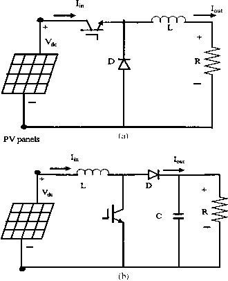 PV panels 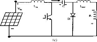 PV panels FIGURE 23.11 (a) Buck converter; (b) boost converter; (c) Buck-boost converter. example, У^рр = к Vqc where /с 0.76. This assumption is reasonably accurate even for large variations in the ceU short-circuit current and temperature. This type of MPPT is probably the most common type. A variation to this method involves periodically open-circuiting the ceU string and measuring the open-circuit voltage. The appropriate value of Vmpp can then be obtained with a simple voltage divider. (b) Closed-loop control. The closed-loop control involves varying the input voltage around the optimum value by giving it a smaU increment or decrement alternately. The effect on the output power is then assessed and a further smaU correction is made to the input voltage. This type of control is caUed a hiU-climbing control. The power output of the PV array is sampled 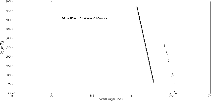 FIGURE 23.12 Typical power/voltage characteristics for increased insolation. Constant power Points 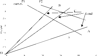 Array voltage FIGURE 23.13 PV array and load characteristics. at an every definite samphng period and compared with the previous value. In the event, when power is increased, the solar array voltage is stepped in the same direction as the previous sample time, but if the power is reduced, the array voltage is stepped in the opposite way, in order to try to operate the PV array at its optimum/maximum power point. To operate the PV array at the maximum power point, perturb and adjust methods can be used in which the current drawn is sampled every few seconds and the resulting power output of the solar ceUs is monitored at regular intervals. When an increased current results in a higher power, it is further increased until the power output starts to decrease. But if the increased PV current results in a lesser amount of power than in the previous sample, then the current is reduced until the maximum power point is reached. 23.2.3.2 Inverters for Stand-Alone PV Systems Inverters convert power from dc to ac, while rectifiers convert it from ac to dc. Many inverters are bi-directional, i.e., they are able to operate in both inverting and rectifying modes. In many stand-alone photovoltaic instaUations, alternating current is needed to operate 230 V (or llOV), 50 Fiz (or 60 Fiz) appliances. Generally stand-alone inverters operate at 12, 24, 48, 96, 120, or 240 V dc, depending on the power level. Ideally, an inverter for a stand-alone photovoltaic system should have the foUowing features: Sinusoidal output voltage Voltage and frequency within the aUowable limits Cable to handle large variation in input voltage Output voltage regulation High efficiency at hght loads Less harmonic generation by the inverter to avoid damage to electronic appliances such as televisions, additional losses, and heating of appliances AbUity to withstand overloading for a short term to take care of higher starting currents from pumps, refrigerators, etc. Adequate protection arrangement for over/undervoltage and frequency, short-circuit, etc. Surge capacity Low idhng and no load losses Low battery voltage disconnect Low audio and RF noise Several different semiconductor devices, such as MOSFETs (metal oxide semiconductor field-effect transistors) and IGBTs (insulated-gate bipolar transistors) are used in the power stage of inverters. Typically MOSFETs are used in units up to 5 kVA and 96 V dc. They have the advantage of low switching losses at higher frequencies. Because the on state voltage drop is 2 V dc, IGBTs are generally used only in systems above 96 V dc. Voltage source inverters are usually used in stand-alone applications. They can be single-phase or three-phase. There are three switching techniques commonly used: square wave, quasi-square-wave, and pulse-width modulation. Square-wave or modified square-wave inverters can supply power tools, resistive heaters, or incandescent lights, which do not require a 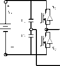 Lf Transformer Load 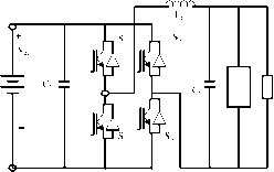 Transformer Load figure 23.14 Single-phase inverter, (a) Half bridge; (b) full bridge. high-quality sine wave for reliable and efficient operation. However, many household appliances require low-distortion sinusoidal waveforms. The use of true sine-wave inverters is recommended for remote area power systems. Pulse-width modulated (PWM) switching is generally used for obtaining sinusoidal output from the inverters. A general layout of a single-phase system, both half-bridge and fuU bridge, is shown in Fig 23.14. In single-phase half bridge (Fig. 23.14a) with two switches, and S2, the capacitors and C2 are connected in series across the dc source. The junction between the capacitors is at the mid-potential. Voltage across each capacitor is Vcl- Switches S and S2 can be switched on/off periodically to produce ac voltage. A filter (Lf and Cf) is used to reduce high-switch-frequency components and to produce sinusoidal output from the inverter. The output of the inverter is connected to the load through a transformer. Figure 23.14b shows the similar arrangement for a fuU-bridge configuration with four switches. For the same input source voltage, the fuU-bridge output is twice as high, and the switches carry less current for the same load power. The power circuit of a three phase, four-wire inverter is shown in Fig. 23.15. The output of the inverter is connected to load via a three-phase transformer (delta/star). The star point of the transformer secondary gives the neutral connection. Three-phase or single-phase can be connected to this system. Alternatively, a center-tap dc source can be used to supply the converter and the midpoint can be used as the neutral. Figure 23.16 shows the inverter efficiency for a typical inverter used in remote-area power systems. It is important to consider that the system load is typically well below the nominal inverter capacity Pnom which results in low conversion efficiencies at loads below 10% of the rated inverter output power. Optimum overaU system operation is achieved if the total energy dissipated in the inverter is minimized. The high conversion efficiency at low power levels of recently developed inverters for grid-connected PV systems shows that there is a significant potential for further improvements in efficiency. Bidirectional inverters convert dc power to ac power (inverter) or AC power to DC power (rectifying) and are becoming very popular in remote area power systems [4, 5]. The principle of a stand-alone single-phase bi-directional inverter used in a PV/Battery/Diesel hybrid system can be explained with reference to Fig. 23.17. A charge controUer is used to interface the PV array and the battery. The inverter has a fuU-bridge configuration realized using four power electro- 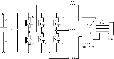 figure 23.15. Stand-alone three-phase four-wire inverter. 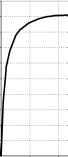 Pinv / Pnom FIGURE 23.16 Typical inverter efficiency curve. nic switches (MOSFET or IGBTs) S1-S4. In this scheme, the diagonaUy opposite switches (S, S4) and (S2, S3) are switched using sinusoidaUy pulse-width modulated gate pulses. The inverter produces sinusoidal output voltage. The inductors X, X2 and the ac output capacitor C2 filter out the high-switch-fi-equency components fi-om the output waveform. Most inverter topologies use a low-frequency (50 or 60 Fiz) transformer to step up the inverter output voltage. In this scheme, the diesel generator and the converter are connected in parallel to supply the load. The voltage sources, diesel and inverter, are separated by the link inductor X. The bidirectional power flow between inverter and the diesel generator can be established. The power flow through the link inductor, X, is Sm = Vi: (23.3) Prn = (VrnV,smS)/X (23.4) Qm = (VJXj(V-V,cosd) (23.5) d = sm-\(XM/(VmVj] (23.6) where 3 is the phase angle between the two voltages. From Eq. (4), it can be seen that the power supphed by the inverter from the batteries (inverter mode) or supplied to the batteries (charging mode) can be controUed by controUing the phase angle 3. The PWM pulses separately control the amplitude of the converter voltage, V, whUe the phase angle with respect to the diesel voltage is varied for power flow. 23.2.3.3 Solar Water Pumping In many remote and rural areas, hand pumps or diesel driven pumps are used for water supply. Diesel pumps consume fossU fuel, affect the environment, need more maintenance, and are less rehable. Photovoltaic (PV)-powered water pumps have received considerable attention because of major developments in the field of solar-ceU materials and power electronic systems technology. 23,2,3,3,1 Types of Pumps Two types of pumps are commonly used for water-pumping applications: Positive displacement and centrifugal. Both centrifugal and positive-displacement pumps can be further classified into those with motors that are surface mounted, and those that are submerged into the water ( submersible ). Displacement pumps have water output directly proportional to the speed of the pump, but almost independent of head. These pumps are used for solar water pumping from deep wells or bores. They may be piston-type pumps or use a diaphragm driven by a cam or rotary screw, or use a progressive cavity system. The pumping rate of these pumps is directly related to the speed, and hence constant torque is desired. Centrifugal pumps are used for low-head applications, especially if they are directly interfaced with the solar panels. Centrifugal pumps are designed for fixed-head applications, and the pressure difference generated increases in relation to the speed of the pump. These pumps are of the rotating-impeUer type, which throws the water radially against a casing shaped so that the momentum of the water is converted into useful pressure for hfting [3]. The centrifugal pumps have relatively high efficiency, but it decreases at lower speeds, which can be a problem for a solar water-pumping system Charge Controller Converter Diesel Voltage V Voltage V 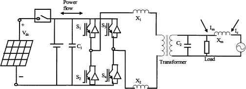 PV panels Battery FIGURE 23.17 Bidirectional inverter system. at times of low light levels. The single-stage centrifugal pump has just one impeller, whereas most borehole pumps are multistage types where the outlet from one impeller goes into the center of another and each one keeps increasing the pressure difference. From Fig. 23.18a, it is quite obvious that the load line is located far away from the P- line. It has been reported that the daily utihzation efficiency for a dc motor drive is 87% for a centrifugal pump compared to 57% for a constant-torque characteristic load. Hence, centrifugal pumps are more compatible with PV arrays. The system operating point is determined by the intersection of the /- V characteristic of the PV array and that of the motor, as shown in Fig. 23.18a. The torque-speed slope is normally large because of the armature resistance being smaU. At the instant of starting, the speed and the back emf are zero. Hence the motor starting current is approximately the short-circuit current of the PV array. Matching the load to the PV source through a maximum-power-point tracker increases the starting torque. The matching of a dc motor depends on the type of load being used. For instance, a centrifugal pump is characterized by having the load torque proportional to the square of speed. The operating characteristics of the system (i.e., PV source, PM dc motor, and load) are at the intersection of the motor and load characteristics as shown in Fig. 23.18b (i.e., points a, h, c, d, e, and / for the centrifugal pump). From Fig. 23.18b, the system utilizing the centrifugal pump as its load tends to start at low solar irradiation (point a) level. However, for systems with an almost constant torque characteristic (Fig. 23.18b, line 1), the start is at almost 50% of one sun (fuU insolation), which results in a short period of operation. 23,2,3,3,2 Types of Motors There are various types of motors available for the PV water pumping applications: dc motors and ac motors. Dc motors are preferred where direct coupling to photovoltaic panels is desired, whereas ac motors are coupled to the solar panels through inverters. Ac motors in general are cheaper than dc motors and are more reliable, but  PV Panel (a)/ (b)..... Torque (Nm) DC Motor-Pump PV array Ш rvlax power point tracker DC-DC converter BDC Motor controller Btushless PC motor Positive displcaement a JLXJmotor Rotor positioning sensing FIGURE 23.18 (a): I-V characteristics of a PV array and two mechanical loads: (1) constant torque and (2) centrifugal pump, (b) Speed torque characteristics of a dc motor and two mechanical loads: (1) helical rotor, (2) centrifugal pump, (c) Block diagram for dc motor-driven pumping scheme, (d): Block diagram for brushless dc motor for PV apphcation. dc motors are more efficient. The dc motors used for solar pumping apphcations are permanent-magnet dc motors with or without brushes. In dc motors with brushes, the brushes are used to deliver power to the commutator and need frequent replacement because of wear and tear. These motors are not suitable for submersible applications unless long transmission shafts are used. Brushless dc permanent-magnet motors have been developed for submersible applications. The ac motors are of the induction motor type, which is cheaper than dc motors and available worldwide. However, they need inverters to change dc input from the PV to ac power. A comparison of the different types of motors used for PV water pumping is given in Table 23.1. 23,2333 Power Conditioning Units for PV Water Pumping Most PV pump manufacturers include power conditioning units (PCUs), which are used for operating the PV panels close to their maximum power point over a range of load conditions and varying insolation levels, and also for power conversion. Dc or ac motor pump units can be used for PV water pumping. In its simplest from, a solar water pumping system comprises of PV array, PCU and DC water pump unit as shown in Figure 23.18(c). In case of lower light levels, high currents can be generated through power conditioning to help in starting the motor- pump units, especially for reciprocating positive-displacement type pumps with constant torque characteristics requiring constant current throughout the operating region. In positive-displacement type pumps, the torque generated by the pumps depends on the pumping head, friction, pipe diameter, etc., and requires a certain level of current to produce the necessary torque. Some systems use electronic controUers to assist in starting and operating the motor under low solar radiation. This is particularly important when using positive-displacement pumps. The solar panels generate dc voltage and current. Solar water pumping systems usually have dc or ac pumps. For dc pumps, the PV output can be directly connected to the pump through maximum power point tracker, or a dc-dc converter can also be used for interfacing for controlled dc output from PV panels. To feed the ac motors, a suitable interface is required for the power conditioning. These PV inverters for the stand-alone applications are very expensive. The aim of power conditioning equipment is to supply the controUed voltage/current output from the converters/inverters to the motor-pump unit. These power-conditioning units are also used for operating the PV panels close to their maximum efficiency for fluctuating solar conditions. The speed of the pump is governed by the avaUable driving voltage. Current lower than the acceptable limit wiU stop the pumping. When the hght level increases, the operating point wiU shift from the maximum-power point. TABLE 23.1 Comparison of the different types of motors used for PV water pumping Types of Motor Advantages Disadvantages Main Features Brushed dc Brushless dc Ac induction motors Simple and efficient for PV applications No complex control circuit is required, as the motor starts without high current surge; these motors will run slowly but do not overheat with reduced voltage Efficient Less maintenance is required No brushes to replace Can use existing ac motor/pump technology, which is cheaper and easily available worldwide; these motors can handle larger pumping requirements Brushes need to be replaced periodically (typical replacement interval is 2000 to 4000 h or 2 years) Available only in small motor sizes Electronic computation adds to extra cost, complexity, and increased risk of failure / malfunction In most cases, oil cooled, cannot be submerged as deeply as water-cooled ac units Needs an inverter to convert DC output from PV to AC, adding cost and complexity Less efficient than dc motor-pump units Prone to overheating if current is not adequate to start the motor or if the voltage is too low Requires maximum power point tracker for optimum performance Available only in small motor sizes Increasing current (by paralleling PV modules) increases the torque; increasing voltage (by series PV modules) increases the speed Growing trend among PV pump manufacturers to use brushless dc motors, primarily for centrifugal-type submersible pumps Available for single or three supply Inverters are designed to regulate frequency to maximize power to the motor in response to changing insolation levels leading to a reduction in efficiency. For centrifugal pumps, there is an increase in current at increased speed, and the matching of /- У characteristics is closer for a wide range of light intensity levels. For centrifugal pumps, the torque is proportional to the square of the speed, and the torque produced by the motors is proportional to the current. Because of the decrease in PV current output, the torque from the motor and consequently the speed of the pump are reduced, resulting in a decrease in back emf and the required voltage for the motor. A maximum-power-point tracker (MPPT) can be used for controlling the voltage/current outputs from the PV inverters to operate the PV close to the maximum operating point for smooth operation of motor-pump units. The dc-dc converter can be used to keep the PV-panel output voltage constant and to help in operating the solar arrays close to the maximum-power point. In the beginning, a high starting current is required to produce a high starting torque. The PV panels cannot supply this high starting current without adequate power conditioning equipment such as a dc-dc converter or by using a starting capacitor. The dc-dc converter can generate the high starting currents by regulating the excess PV array voltage. The dc-dc converter can be a boost or buck converter. Brushless dc motors (BDCM) and hehcal rotor pumps can also be used for PV water pumping [20]. BDCMs are a self-synchronous type of motor characterized by trapezoidal waveforms for back emf and air flux density. They can operate off a low-voltage dc supply that is switched through an inverter to create a rotating stator field. The current generation of BDCMs use rare earth magnets on the rotor to give high air-gap flux densities and are weU suited to solar application. The block diagram of such an arrangement, shown in Fig. 23.18d, consists of PV panels, a dc-dc converter, an MPPT, and a brushless dc motor. The PV inverters are used to convert the dc output of the solar arrays to an ac quantity so as to run the ac motor-driven pumps. These PV inverters can be of the variable-frequency type, which can be controUed to operate the motors over a wide range of loads. The PV inverters may involve impedance matching to match the electrical characteristics of the load and array. The motor-pump unit and PV panels operate at their maximum efficiencies [7]. The MPPT is also used in the power conditioning. To keep the voltage stable for the inverters, the dc-dc converter can be used. The inverter/converter has the capability of injecting high-switch-frequency components, which can lead to overheating and losses, care must be taken in doing this. The PV arrays are usually connected in series, paraUel, or a combination of series and paraUel configurations. The function of power electronic interface, as mentioned before, is to convert the dc power from the array to the required voltage and frequency to drive the ac motors. The motor-pump system load should be such that the array operates close to its maximum power point at aU solar insolation levels. There are mainly three types solar powered water pumping systems, as shown in Fig. 23.19. The first system shown in Fig 23.19a is an imported commercially avaUable unit, which uses a specially wound low-voltage induction-motor-driven submersible pump. Such a low-voltage motor permits the PV array voltage to be converted to ac without using a step-up transformer. The second system, shown in Fig. 23.19b, makes use of a conventional off-the-shelf 415-V, 50-Hz, induction motor [6]. This scheme needs a step-up transformer to raise inverter output voltages to high voltage. The third scheme as shown in Fig. 23.19c comprises of a dc-to-dc converter, an inverter that switches at high frequency, and a mains-voltage motor-driven pump. To get the optimum discharge (Q) at a given insolation level, the efficiency of the dc-dc converter and the inverter should be high. So the purpose should be to optimize the output from the PV array, motor, and pump. The principle used here is to vary the duty cycle of a dc-to-dc converter so that the output voltage is maximum. The dc-to-dc converter is used to boost the solar array voltage to ehminate the need for a step-up transformer and to operate the array at the maximum power point. The three-phase inverter used in the interface is designed to operate in a variable-frequency mode over the range of 20 to 50-Hz, which is the practical limit for most 50-Hz induction motor applications. The block diagram for PV panel 3 Phase Inverter without step-глр transformer Low voltage AC motor Mbtor-punqvj 3 Phase Inverter Ь 3 Phase step-up transformer NHains voltage voltage AC motor Nlotor-pump 1If I H 3 Phase Inverter IHains voltage voltage AC motor Motor-punrqi J FIGURE 23.19 Block diagrams for various ac motor-driven pumping schemes. PV Panel Motor Рштцэ . Voltage a Frequency Control Processor FIGURE 23.20 Block diagram for voltage/frequency control. frequency control is given in Fig. 23.20. This inverter would be suitable for driving permanent-magnet motors by incorporating additional circuitry for position sensing of the motors shaft. Also, the inverter could be modified, if required, to produce higher output frequencies for high-speed permanent-magnet motors. The inverter has a three-phase fuU-bridge configuration implemented by MOSFET power transistors. 23.2.4 PV-Diesel Systems Photovoltaic-diesel hybrid energy systems generate ac electricity by combining a photovoltaic array with an inverter, which can operate alternately or in parallel with a conventional engine-driven generator. They can be classified according to their configuration as follows [8]: 1. Series hybrid energy systems 2. Switched hybrid energy systems 3. ParaUel hybrid energy systems An overview of the three most common system topologies is presented by Bower [9]. In the following comparison, typical PV-diesel system configurations are described. 23.2.4.1 Series Configuration Figure 23.21 shows a series PV-diesel hybrid energy system. To ensure reliable operation of series hybrid energy systems, both Diesel Generator 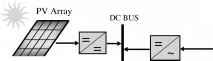 Solar Controller  Battery Charger FIGURE 23.21 Series PV-diesel hybrid energy system. the diesel generator and the inverter have to be sized to meet peak loads. This results in a typical system operation where a large fraction of the generated energy is passed through the battery bank, resulting in increased cycling of the battery bank and reduced system efficiency. Ac power delivered to the load is converted from dc to regulated ac by an inverter or a motor generator unit. The power generated by the diesel generator is first rectified and subsequently converted back to ac before being supplied to the load, which leads to significant conversion losses. The actual load demand determines the amount of electrical power delivered by the photovoltaic array, the battery bank, or the diesel generator. The solar controller prevents overcharging of the battery bank from the PV generator when the PV power exceeds the load demand and the batteries are fully charged. It may include maximum power point tracking to improve the utUization of the avaUable photovoltaic energy, although the energy gain is marginal for a weU-sized system. The system can be operated in manual or automatic mode, with the addition of appropriate battery voltage sensing and start/stop control of the engine-driven generator. The advantages of such a system include the foUowing: The engine-driven generator can be sized to be optimally loaded whUe supplying the load and charging the battery bank, untU a battery state-of-charge (SOC) of 70-80% is reached. No switching of ac power between the different energy sources is required, which simphfies the electrical output interface. The power supphed to the load is not interrupted when the diesel generator is started. The inverter can generate a sine-wave, modified square wave, or square wave, depending on the application. The disadvantages are: The inverter cannot operate in paraUel with the engine-driven generator; therefore, the inverter must be sized to supply the peak load of the system. Converter Inverter The battery bank is cycled frequently, which shortens its lifetime. The cycling profile requires a large battery bank to limit the depth-of-discharge. The overaU system efficiency is low, since the diesel cannot supply power directly to the load; Inverter failure results in complete loss of power to the load, unless the load can be supphed directly from the diesel generator for emergency purposes. 23.2.4.2 Switched Configuration Despite its operational limitations, the switched configuration as shown in Fig. 23.22 remains one of the most common instaUations today. It allows operation with either the engine-driven generator or the inverter as the ac source, yet no paraUel operation of the main generation sources is possible. The diesel generator and the renewable energy source can charge the battery bank. The main advantage compared with the series system is that the load can be supplied directly by the engine-driven generator, which results in a higher overaU conversion efficiency. Typically, the diesel generator power wiU exceed the load demand, with excess energy being used to recharge the battery bank. During periods of low electricity demand the diesel generator is switched off and the load is supphed from the PV array together with stored energy. Switched hybrid energy systems can be operated in manual mode, although the increased complexity of the system makes it highly desirable to include an automatic controUer, which can be implemented with the addition of appropriate battery voltage sensing and start/stop control of the engine-driven generator. The advantages of this system are: The inverter can generate a sine-wave, modified square wave, or square wave, depending on the particular application. The diesel generator can supply the load directly, therefore improving the system efficiency and reducing the fuel consumption. The disadvantages are: Power to the load is interrupted momentarily when the ac power sources are transferred. The engine-driven alternator and inverter are typically designed to supply the peak load, which reduces their efficiency at part-load operation. 23.2.4.3 Parallel Configuration The parallel configuration shown in Fig. 23.23 aUows aU energy sources to supply the load separately at low or medium load demand, as weU as supplying peak loads from combined sources by synchronizing the inverter with the alternator output waveform. The bidirectional inverter can charge the battery bank (rectifier operation) when excess energy is avaUable from the engine-driven generator, as weU as act as a dc-ac converter (inverter operation). The bidirectional inverter may provide peak shaving as part of the control strategy when the engine-driven generator is overloaded. ParaUel hybrid energy systems are characterized by two significant improvements over the series and switched system configurations. 1. The inverter plus the diesel generator capacity rather than their individual component ratings hmit the maximum load that can be supphed. Typically, this wiU lead to a doubling of the system capacity. The capability to synchronize the inverter with the diesel generator aUows greater flexibUity to optimize the operation of the system. Future systems should be sized with a reduced peak capacity of the diesel generator, which results in a higher fraction of directly used energy and hence higher system efficiencies. 2. By using the same power electronic devices for both inverter and rectifier operation, the number of system components is minimized. Additionally, wiring and system instaUation costs are reduced through the integration of aU power conditioning devices in one central power unit. This highly integrated system concept has advantages over a more modular approach to system design, but it may prevent convenient system upgrades when the load demand increases. PV Array 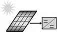 2 BUS Diesel Generator Solar Controller 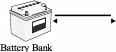 Battery Charger 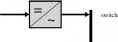 chanse-over - Inverter AC Load FIGURE 23.22 Switched PV-diesel hybrid energy system. 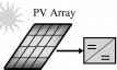 - BUS Diesel Generator Solar Controller  Bi-directional Inverter AC Load FIGURE 23.23 Parallel PV-diesel hybrid energy system. 1 ... 52 53 54 55 56 57 58 ... 91 |
|
© 2026 AutoElektrix.ru
Частичное копирование материалов разрешено при условии активной ссылки |