 |
 |
 |
| Главная Журналы Популярное Audi - почему их так назвали? Как появилась марка Bmw? Откуда появился Lexus? Достижения и устремления Mercedes-Benz Первые модели Chevrolet Электромобиль Nissan Leaf |
Главная » Журналы » Metal oxide semiconductor 1 ... 53 54 55 56 57 58 59 ... 91 The paraUel configuration offers a number of potential advantages over other system configurations. These objectives can only be met if the interactive operation of the individual components is controUed by an inteUigent hybrid energy management system. Although todays generation of paraUel systems includes system controUers of varying complexity and sophistication, they do not optimize the performance of the complete system. Typically, both the diesel generator and the inverter are sized to supply anticipated peak loads. As a result, most parallel hybrid energy systems do not utihze their capabUity of paraUel, synchronized operation of multiple power sources. The advantages of this system include the foUowing: The system load can be met in an optimal way. Diesel generator efficiency can be maximized. Diesel generator maintenance can be minimized. A reduction in the rated capacities of the diesel generator, battery bank, inverter, and renewable resources is feasible, whUe also meeting the peak loads. The disadvantages are: Automatic control is essential for the reliable operation of the system. The inverter has to be a true sine-wave inverter with the abihty to synchronize with a secondary ac source. System operation is less transparent to the untrained user of the system. 23.2.4.4 Control of PV-Diesel Hybrid Systems The design process of hybrid energy systems requires the selection of the most suitable combination of energy sources, power-conditioning devices, and energy-storage system, together with the implementation of an efficient energy-dispatch strategy. System simulation software is an essential tool to analyze and compare possible system combinations. The objective of the control strategy is to achieve optimal operational performance at the system level. Inefficient operation of the diesel generator and dumping of excess energy is common for many remote-area power supplies operating in the field. Component maintenance and replacement contributes significantly to the hfe-cycle cost of systems. These aspects of system operation are clearly related to the selected control strategy and have to be considered in the system design phase. Advanced system control strategies seek to reduce the number of cycles and the depth-of-discharge for the battery bank, run the diesel generator in its most efficient operating range, maximize the utUisation of the renewable resource, and ensure high reliabUity of the system. Because of the varying nature of the load demand, the fluctuating power supplied by the photovoltaic generator, and the resulting variation of battery SOC, the hybrid energy system controUer has to respond to continuously changing operating conditions. Figure 23.24 shows different operating modes for a PV single-diesel system using a typical diesel dispatch strategy. Mode (I): The base load, which is typically experienced at night and during the early morning hours, is supplied by energy stored in the batteries. Photovoltaic power is not avaUable and the diesel generator is not started. Mode (II): PV power is supplemented by stored energy to meet the medium load demand. Mode (III): Excess energy is available from the PV generator, which is stored in the battery. The medium load demand is supplied from the PV generator. Mode (IV): The diesel generator is started and operated at its nominal power to meet the high evening load. Excess energy avaUable from the diesel generator is used to recharge the batteries. Mode (V): The diesel generator power is insufficient to meet the peak load demand. Additional power is supplied from the batteries by synchronizing the inverter ac output voltage with the alternator waveform. Mode (VI): The diesel generator power exceeds the load demand, but it is kept operational untU the batteries are recharged to a high state-of-charge level. In principle, most efficient operation is achieved if the generated power is supplied directly to the load from aU energy sources, which also reduces cycling of the battery bank. Fiowever, since diesel generator operation at light loads is inherently inefficient, it is common practice to operate the engine-driven generator at its nominal power rating and to recharge the batteries from the excess energy. The selection of the most efficient control strategy depends on fuel, maintenance and component-replacement cost, the system configuration, and environmental conditions, as weU as constraints imposed on the operation of the hybrid energy system. 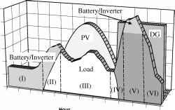 Diesel Energy PV Energy Hourly Load FIGURE 23.24 Operating modes for a PV single-diesel hybrid energy system. 23.2.5 Grid Connected PV Systems Utility interactive inverters not only condition the power output of the photovoltaic arrays but ensure that the PV system output is fully synchronized with the utility power. These systems can be batteryless or with battery backup. Systems with battery storage (or a flywheel) provide additional power-supply reliability. The grid connection of photovoltaic systems is gathering momentum because of various rebate and incentive schemes. This system aUows the consumer to feed its own load utilizing the available solar energy, and the surplus energy can be injected into the grid under the energy buy-back scheme to reduce the payback period. Grid-connected PV systems can become a part of the utility system. The contribution of solar power depends on the size of system and the load curve of the house. When the PV system is integrated with the utility grid, a two-way power flow is established. The utility grid wiU absorb excess PV power and wiU feed the house at night and at instants when the PV power is inadequate. The utility companies are encouraging this scheme in many parts of the world. The grid-connected system can be classified as foUows: Rooftop application of grid-connected PV system Utility-scale large system For smaU household PV apphcations, a roof-mounted PV array can be the best option. Solar ceUs provide an environmentally clean way of producing electricity, and rooftops have always been the ideal place to put them. With a PV array on the rooftop, the solar-generated power can supply residential load. The rooftop PV systems can help in reducing the peak summer load to the benefit of utUity companies by feeding the household lighting, cooling, and other domestic loads. The battery storage can further improve the reliability of the system at times of low insolation level, at night or on cloudy days. But the battery storage has some inherent problems, such as maintenance and higher cost. For roof-integrated apphcations, the solar arrays can be either mounted on the roof or directly integrated into the roof. If the roof integration does not aUow for an air channel behind the PV modules for ventilation purposes, then it can increase the ceU temperature during the operation, consequently leading to some energy losses. The disadvantage of the rooftop apphcation is that the PV array orientation is dictated by the roof. In cases, where the roof orientation differs from the optimal orientation required for the cells, the efficiency of the entire system would be suboptimal. Utility interest in PV has centered around the large grid-connected PV systems. In Germany, the United States, Spain, and several other parts of the world, some large PV-scale plants have been instaUed. The utUities are more inchned toward large-scale, centralized power supplies. The PV systems can be centralized or distributed systems. Grid-connected PV systems must observe the islanding situation, when the utUity supply fails. In case of islanding, the PV generators should be disconnected from mains. PV generators can continue to meet only the local load, if the PV output matches the load. If the grid is reconnected during islanding, transient overcurrents can flow through the PV system inverters, and protective equipment such as circuit breakers may be damaged. Islanding control can be achieved through inverters or via the distribution network. Inverter controls can be designed on the basis of detection of grid voltage or measurement of impedance, frequency variation, or increase in harmonics. Protection must be designed for islanding, short circuits, over/under voltages/currents, grounding and lightning etc. The importance of the power generated by the PV system depends on the time of the day, especially when the utUity is experiencing peak load. The PV plants are weU suited to summer peaking, but it depends upon the climatic condition of the site. PV systems being investigated for use as peaking stations would be competitive for load management. The PV users can defer their load by adopting load management to get the maximum benefit out of the grid-connected PV plants and feeding more power into the grid at the time of peak load. The assigned capacity credit is based on the statistical probability that the grid can meet peak demand [3]. The capacity factor during peaks is very simUar to that of conventional plants, and simUar capacity credit can be given for PV generation, except at times when the PV plants are generating very much less power, unless adequate storage is provided. With the instaUation of PV plants, the need for extra transmission hues and transformers can be delayed or avoided. The distributed PV plants can also contribute in providing reactive power support to the grid and reduce the burden on VAR compensators. 23.2.5.1 Inverters for Grid-Connected Applications The power conditioner is the key link between the PV array and mains in the grid-connected PV system. It acts as an interface that converts dc current produced by the solar cells into UtUity-grade ac current. The PV system behavior relies heavily on the power-conditioning unit. The inverters must produce good-quality sine-wave output, must foUow the frequency and voltage of the grid, and must extract maximum power from the solar ceUs with the help of a maximum-power-point tracker. The inverter input stage varies the input voltage untU the maximum power point on the /- V curve is found. The inverter must monitor aU the phases of the grid, and inverter output must be controlled in terms of voltage and frequency variation. A typical grid-connected inverter may use a pulse-width modulation (PWM) scheme and operate in the range of 2 kHz up to 20 kHz. 23.2.5.2 Inverter Classifications The inverters used for grid interfacing are broadly classified as voltage-source inverters (VSI) and current-source inverters (CSI); whereas the inverters based on the control schemes can be classified as current-controUed inverters (CCI) and voltage-controUed inverters (VCI). The source is not necessarily characterized by the energy source for the system. It is a characteristic of the topology of the inverter. It is possible to change from one source type to another source type by the addition of passive components. In the voltage-source inverter (VSI), the dc side is made to appear to the inverter as a voltage source. The voltage-source inverters have a capacitor in paraUel across the input, whereas the current-source inverters have an inductor in series with the dc input. In the current-source inverter (CSI), the dc source appears as a current source to the inverter. Solar arrays are fairly good approximation to a current source. Most PV inverters are voltage source, even though the PV is a current source. Current-source inverters are generally used for large motor drives although there have been some PV inverters built using a current source topology. The voltage-source inverter is more popular, with the PWM voltage-source inverter (VSI) dominating the sine-wave inverter topologies. Fig 23.25a shows a single-phase fuU bridge bidirectional voltage source inverter (VSI) with (a) voltage control and phase shift (3) control. The active power transfer from the PV panels is accomplished by controUing the phase angle 3 between the converter voltage and the grid voltage. The converter voltage follows the grid voltage. Figure 23.25b shows the same voltage source inverter operated as a current-controlled inverter (CSI). The objective of this scheme is to control active and reactive components of the current fed into the grid using pulse-width modulation techniques. 23.2.5.3 Inverter Types Various types of inverters are in use for grid-connected PV applications, including the foUowing: Line-commutated inverter Self-commutated inverter PV inverter with high-frequency transformer 23,2,5,3,1 Line-Commutated Inverter Line-commutated inverters are generally used for electric-motor apphcations. The power stage is equipped with thyristors. A maximum-power tracking control is required in the control algorithm for solar application. The basic diagram for a single-phase line-commutated inverter is shown in Fig. 23.26 [2]. The driver circuit has to be changed to shift the firing angle from rectifier operation {0° < ф < 90°) to inverter operation (90° < Ф < 180°). Six-pulse or 12-pulse inverters are used for grid interfacing, but 12-pulse inverters produce fewer harmo- IVcl, 5 Jib -ji 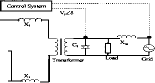 PV panels Control System Ш Transformer Load C3rid PV panels FIGURE 23.25 (a) Grid-interactive VSI; (b) grid-interactive CSI.  PV Array Vdc 240 V , \ FIGURE 23.26 Line-commutated single-phase inverter. C3rid nics. Thyrsistor-type inverters require a low-impedance grid interface connection for commutation purposes. If the maximum power available from the grid connection is less than twice the rated PV inverter power, then the line-commutated inverter should not be used [2]. The line-commutated inverters are cheaper but can lead to poor power quality. The harmonics injected into the grid can be large unless taken care of by employing adequate filters. These line-commutated inverters also have poor power factors that require additional control to improve them. Transformers can be used to provide electrical isolation. To suppress the harmonics generated by these inverters, tuned filters are employed and reactive power compensation is required to improve the lagging power factor. 23,2,53,2 Self-Commutated Inverter A switch-mode inverter using pulse-width modulated (PWM) switching control can be used for the grid connection of PV systems. The basic block diagram for this type of inverter is shown in Fig. 23.27. The inverter bridges may consist of bipolar transistors, MOSFET transistors, IGBTs, or GTOs, depending on the type of apphcation. GTOs are used for higher-power applications, whereas IGBTs can be switched at higher frequencies, i.e., 20 kHz, and are generally used for many grid-connected PV apphcations. Most present-day inverters are self-commutated sine-wave inverters. Based on the switching control, voltage-source inverters can be further classified as foUows: PWM (pulse width modulated) inverters Square-wave inverters Single-phase inverters with voltage canceUations Programmed harmonic elimination switching Current-controUed modulation  Transformer N Л \ \ 23,2,5,3,3 PV Inverter with High-Frequency Transformer The 50-Hz transformer for a standard PV inverter with PWM switching scheme can be very heavy and costly. When using frequencies more than 20 kHz, a ferrite core transformer can be a better option [2]. A circuit diagram of a grid-connected PV system using high frequency transformer is shown in Fig. 23.28. The capacitor on the input side of the high-frequency inverter acts as a filter. The high-frequency inverter with pulse-width modulation is used to produce a high-frequency ac across the primary winding of the high-frequency transformer. The secondary voltage of this transformer is rectified using a high-frequency rectifier. The dc voltage is interfaced with a thyristor inverter through a low-pass inductor filter and hence connected to the grid. The line current is required to be sinusoidal and in phase with the hne voltage. To achieve this, the line voltage (V) is measured to establish the reference waveform for the line current /*. This reference current /* rem. 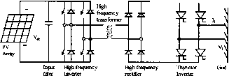 FIGURE 23.28 PV inverter with high-frequency transformer. 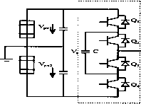 FIGURE 23.27 Self-commutated inverter with PWM switching. Inverter FIGURE 23.29 Half-bridge diode-clamped three-level inverter. Ш < -t -nnm. PV panels Boost Choppcf Voltage Source Inverter FIGURE 23.30 Noninsulated voltage source. Ю о > I multiplied by the transformer ratio gives the reference current at the output of the high-frequency inverter. The inverter output can be controUed using current-controls technique [10]. These inverters can be used with low-frequency or high-frequency transformer isolation. The low-frequency (50/60 Fiz) transformer of a standard inverter with pulsewidth modulation is a very heavy and bulky component. For residential grid interactive rooftop inverters below 3-kW rating, high-frequency transformer isolation is often preferred. 23,2,5,3,4 Other PV Inverter Topologies In this section, some of the inverter topologies discussed in various research papers are discussed. Multilevel Converters Multilevel converters can be used with large PV systems where multiple PV panels can be configured to create voltage steps. These multUevel voltage source converters can synthesize the ac output terminal voltage from different levels of dc voltages and can produce staircase waveforms. This scheme involves less complexity and needs less filtering. One of the schemes (half-bridge diode-clamped three-level inverter [11]) is given in Fig. 23.29. There is no transformer in this topology. MultUevel converters can be beneficial for large systems in terms of cost and efficiency. Problems associated with shading and malfunction of PV units need to be addressed. Noninsulated Voltage Source In this scheme [12], a string of low-voltage PN panels or one high-voltage unit can be coupled with the grid through a dc-to-dc converter and voltage-source inverter. This topology is shown in Fig. 23.30. A PWM switching scheme can be used to generate ac output. A filter has been used to reject the switching components. Non-insulated Current Source This type of configuration is shown in Fig. 23.31. Non-insulated current source inverters [12] can be used to interface the PV panels with the grid. This Jc Jr PV panels -o o- -o o  FIGURE 23.31 Noninsulated current source. topology involves low cost and can provide better efficiency. Appropriate controUers can be used to reduce current harmonics. Buck Converter with Half-bridge Transformer Link PV panels are connected to grid via a buck converter and half-bridge as shown in Fig. 23.32. In this, high-frequency PWM switching has been used at the low-voltage photovoltaic side to generate an attenuated rectified 100-Fiz sine wave current waveform [13]. A half-wave bridge is utihzed to convert this output to a 50-Fiz signal suitable for grid interconnection. To step up the voltage, the transformer has also been connected before the grid connection point. Flyback Converter This converter topology steps up the PV voltage to dc bus voltage. The PWM-operated converter has been used for grid connection of a PV system in Fig. 23.33. This scheme is less complex and has fewer switches. Flyback converters can be beneficial for remote areas because of their complex power-conditioning components. Interface using Paralleled PV Panels A low-voltage ac bus scheme [14] can be a comparatively efficient and cheaper option. One of the schemes is shown in Fig. 23.34. A number of smaUer PV units can be paraUeled together and then Grid 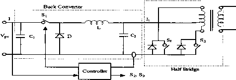 FIGURE 23.32 Buck converter with half-bridge transformer link. Panel В 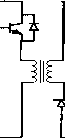 FIGURE 23.33 Flyback converter. connected to a single low-frequency transformer. In this scheme, PV panels are connected in parallel rather than series to avoid problems associated with shading or malfunction of one of panels in series connection. 23.2.5.4 Power Control through PV Inverters The system shown in Fig. 23.35a shows control of power flow onto the grid. This control can be analog or a microprocessor system. This control system generates the waveforms and regulates the waveform amplitude and phase to control the power flow between the inverter and the grid. The grid-interfaced PV inverters, voltage-controlled (VCI) or current-controlled (CCI), have the potential of bidirectional power flow. They not only can feed the local load, but also can export the excess active and reactive power to the utility grid. An appropriate controller is required in order to avoid any error in power export due to errors in synchronization, which can overload the inverter. A simple grid-inverter interface with a first-order filter and the phasor diagram [15] are shown in Figs. 23.35a and 23.35b. In the case of voltage controUers, the power equation can be written as [10]: or S = pwm sin д -\- j pwm --cosd - 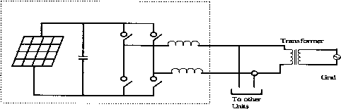 PVUmt 23-36 FIGURE 23.34 Converter using parallel PV units. Transfonrier и . V, PV inverter 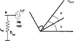 FIGURE 23.35 (a) Simple grid interface system; (b) phasor diagram of grid-integrated PV. whereas for the current controUers [16]: S=v cose+j[V sine] (23.7) It has been observed that the inverter rated power export is achieved at = 5°. When using a voltage controller for grid connected PV inverter, it has been observed that a slight error in the phase of synchronising waveform can grossly overload the inverter whereas a current controUer is much less susceptible to voltage phase shifts [15]. For this reason, the current controllers are better suited for the control of power export from the PV inverters to the utility grid since they are less sensitive to errors in synchronizing sinusoidal voltage waveforms. A prototype current-controUed-type power conditioning system has been developed by the first author and tested on a weak rural feeder line at Kalbarri in Western Australia [17]. The choice may be between additional conventional generating capacity at a centrahzed location or adding smaller distributed generating capacities using renewable energy sources such as PV. The latter option can have a number of advantages: The additional capacity is added wherever it is required without adding power-distribution infrastructure. This is a critical consideration where the power lines and transformers are already at or close to their maximum ratings. The power conditioning system can be designed to provide much more than just a source of real power, for minimal extra cost. A converter providing real power needs only a slight increase in ratings to handle significant amounts of reactive or even harmonic power. The same converter that converts dc photovoltaic power to ac power can simultaneously provides reactive power support to the weak utUity grid. The block diagram of the power conditioning system used in the Kalbarri project is shown in the Fig. 23.36. This CC-VSI operates with a relatively narrow switching frequency band near 10 kFiz. The control diagram indicates the basic operation of the power conditioning system. The two outer control loops operate to independently control the real and reactive power flow from the PV inverter. The real power is controUed by an outer maximum-power-point tracking (MPPT) algorithm with an inner dc hnk voltage-control loop providing the real current magnitude request. and hence the real power export through PV converter are controUed through the dc link-voltage regulation. The dc link voltage is maintained at a reference value by a PI control loop, which gives the real current reference magnitude as its output. At regular intervals, the dc link voltage is scanned over the entire voltage range to check that the algorithm is operating on the absolute MPP and is not stuck around a local MPP. During the night, the converter can stiU be used to regulate reactive power of the grid-connected system, although it cannot provide active power. During this time, the PI controUer maintains a minimum dc link voltage to allow the power-conditioning system to continue to operate, providing the necessary reactive power. The ac line voltage regulation is provided by a separate reactive power control, which provides the reactive current magnitude reference Iq. The control system has a simple transfer function, which varies the reactive power command in response to ac voltage fluctuations. Common to the outer real and reactive power control loops is an inner higher bandwidth ZACE current control loop. L* is in phase with 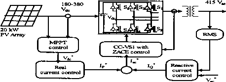 FIGURE 23.36 Block diagram of Kalbarri power-conditioning system. String 1 string 2 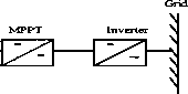 String 1 MPPT Inverter Grid String 3 FIGURE 23.37 Central-plant inverter. the line voltages, and /q is at 90° to the line voltages. These are added together to give one (per phase) sinusoidal converter current reference waveform (/*). The GG-VSI control consists of analog and digital circuitry that acts as a ZAGE transconductance amplifier in converting /* into ac power currents [18]. 23.2.5.5 System Configurations The utility-compatible inverters are used for power conditioning and synchronization of PV output with the utility power. In general, four types of batteryless grid connected PV system configurations have been identified: Gentral-plant inverter Multiple-string dc-dc converter with single-output inverter Multiple-string inverter Module-integrated inverter 23.2.5.5.1 Central-Plant Inverter In the central-plant inverter, usually a large inverter is used to convert dc power output of PV arrays to ac power. In this system, the PV modules are serially strung to form a panel (or string), and several such panels are connected in paraUel to a single dc bus. The block diagram of such a scheme is shown in Fig. 23.37. 23.2.5.5.2 Multiple-String dc/dc Converter In the muhiple-string dc-dc converter, as shown in Fig. 23.38, each string wiU have a boost dc-dc converter with transformer isolation. There wiU be a common dc link, which feeds a transformerless inverter. 23.2.5.5.3 Multiple-String Inverter Figure 23.39 shows the block diagram of a multiple-string inverter system. In this scheme, several modules are connected in series on the dc side String 2 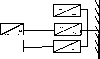 String 3 FIGURE 23.39 Multiple-string inverter. to form a string. The output from each string is converted to ac through a smaUer individual inverter. Many such inverters are connected in paraUel on the ac side. This arrangement is not badly affected by shading of the panels. It is also not seriously affected by inverter faUure. 23,2,5,5,4 Module-Integrated Inverter In the module-integrated inverter system (Fig. 23.40), each module (typically 50 W to 300 W) wiU have a smaU inverter. No cabling is required. It is expected that a high volume of smaU inverters wiU bring down the cost. 23.2.5.6 Grid-Compatible Inverter Characteristics The characteristics of the grid-compatible inverters are: Response time Power factor Frequency control Harmonic output Synchronization Fault current contribution Dc current injection Protection The response time of the inverters must be extremely fast and governed by the bandwidth of the control system. The absence of rotating mass and the use of semiconductor switches aUow inverters to respond in a miUisecond time frame. The power factor of the inverters is traditionally poor because of the displacement power factor and harmonics. But with the latest developments in inverter technology, it is possible to maintain a power factor close to unity. The converters/inverters have String 1 MPPT String 2 Grid Inverter String 3 FIGURE 23.38 Multiple-string dc/dc converter. IVIodule 1 Inveriier Grid 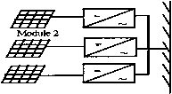 Modules FIGURE 23.40 Module-integrated inverter. the capability of creating large voltage fluctuations by drawing reactive power from the utility rather than supplying it [19]. With proper control, inverters can provide voltage support by importing/exporting reactive power to push/puU toward a desired set point. This function would be of more use to the utilities as it can assist in the regulation of the grid system at the domestic consumer level. The frequency of the inverter output waveshape is locked to the grid. Frequency bias is where the inverter frequency is deliberately made to run at, say, 53 Fiz. When the grid is present, this wiU be puUed down to the nominal 50 Fiz. If the grid fails, it wiU drift upward toward 53 Fiz and trip on overfrequency. This can help in preventing islanding. Fiarmonic output from inverters has traditionally been very poor. Old thyristor-based inverters operated with slow switching speeds and could not be pulse-width modulated. This resulted in inverters known as six-pulse or 12-pulse inverters. The harmonics so produced from the inverters can be injected into the grid, resulting in losses, heating of appliances, tripping of protection equipment, and poor power quality, the number of pulses being the number of steps in a sine-wave cycle. With the present advances in power-electronics technology, inverter controls can be made very good. PWM inverters produce high-quality sine waves. The harmonic levels are very low and can be lower than those of common domestic appliances. If harmonics are present in the grid voltage waveform, harmonic currents can be induced in the inverter. These harmonic currents, particularly those generated by a voltage-controlled inverter, will in fact help in supporting the grid. These are good harmonic currents. This is the reason that the harmonic current output of inverters must be measured onto a clean grid source so that only the harmonics being produced by the inverters are measured. Synchronization of inverters with the grid is performed automatically and typically uses zero-crossing detection on the voltage waveform. An inverter has no rotating mass and hence has no inertia. Synchronization does not involve the acceleration of a rotating machine. Consequently, the reference waveforms in the inverter can be jumped to any point required within a sampling period. If phase-locked loops are used, the jump could take up a few seconds. Phase-locked loops are used to increase the immunity to noise. This aUows the synchronization to be based on several cycles of zero-crossing information. The response time for this type of locking wiU be slower. PV panels produce a current that is proportional to the amount of light faUing on them. The panels are normally rated to produce 1000 W/m at 25°C. Under these conditions, the short circuit current possible from these panels is typically only 20% higher than the nominal current, whereas it is extremely variable for wind. If the solar radiation is low then the maximum current possible under short circuit is going to be less than the nominal fuU-load current. Consequently, PV systems cannot provide short-circuit capacity to the grid. If a battery is present, the fault current contribution is limited by the inverter. With battery storage, it is possible for the battery to provide the energy. Fiowever, inverters are typically limited to between 100% and 200% of nominal rating under current-limit conditions. The inverter needs to protect itself against short circuits because the power electronic components wiU typically be destroyed before a protection device such as a circuit breaker trip. In case of inverter malfunction, inverters have the capability to inject the dc components into the grid. Most utilities have guidehnes for this purpose. A transformer must be installed at the point of connection on the ac side to prevent dc from entering the utility network. The transformer can be omitted when a dc detection device is installed at the point of connection on the ac side in the inverter. The dc injection is essentially caused by the reference or power electronics device producing a positive half-cycle that is different from the negative half-cycle resulting into the dc component in the output. If the dc component can be measured, it can then be added into the feedback path to eliminate the dc quantity. 23,2,5,6,1 Protection Requirements A minimum requirement to facilitate the prevention of islanding is that the inverter energy system protection operates and isolates the inverter energy system from the grid if any of the foUowing occurs: Overvoltage Undervoltage Overfrequency Underfrequency These limits may be either factory-set or site-programmable. The protection voltage operating points may be set in a narrower band if required, e.g., 220 V to 260 V. In addition to the passive protection detailed above, and to prevent the situation where islanding may occur because multiple inverters provide a frequency reference for one another, inverters must have an accepted active method of islanding prevention foUowing grid faUure, e.g., frequency drift or impedance measurement. Inverter controls for islanding can be designed on the basis of detection of grid voltage, measurement of impedance, frequency variation, or increase in harmonics. This function must operate to force the inverter output outside the protection tolerances specified previously, thereby resulting in isolation of the inverter energy system from the grid. The maximum combined operation time of both passive and active protections should be 2 seconds after grid failure under aU local load conditions. If frequency shift is used, it is recommended that the direction of shift be down. The inverter energy system must remain disconnected from the grid untU the reconnection conditions are met. Some inverters produce high-voltage spikes, especially at light load, which can be dangerous for the electronic equipment. IEEE P929 gives some idea of the permitted voltage hmits. If the inverter energy system does not have the preceding frequency features, the inverter must incorporate an ahernate antiislanding protection feature that is acceptable to the relevant electricity distributor. If the protection function above is to be incorporated in the inverter, it must be type tested for compliance with these requirements and accepted by the relevant electricity distributor. Otherwise, other forms of external protection relaying are required that have been type tested for compliance with these requirements and approved by the relevant electricity distributor. The inverter must have adequate protection against short-circuit, other faults, and overheating of inverter components. 23.3 Power Electronics for Wind Power Systems In the rural United States, the first windmiU to generate electricity was commissioned in 1890. Today, large wind generators are competing with utilities in supplying clean power economically. The average wind turbine size has been 300-600 kW until recently New wind generators of 1-3 MW have been developed and are being installed worldwide, and prototypes of even higher capacity are under development. Improved wind turbine designs and plant utilization have resulted in significant reduction in wind energy generation cost from 35 cents per kWh in 1980 to less than 5 cents per kWh in 1999 in locations where wind regime is favorable. At this generation cost, wind energy has become one of the cheapest power sources. The main factors that have contributed to the wind power technology development are: High-strength fiber composites for manufacturing large, low-cost blades Variable-speed operation of wind generators to capture maximum energy Advances in power electronics and decreased associated cost Improved plant operation and efficiency Economy of scale due to availability of large wind generation plants Accumulated field experience improving the capacity factor Computer prototyping by accurate system modehng and simulation Table 23.2 is for wind sites with average annual wind speed of 7 m/s at 30 m hub height. Since the 1980s, wind technology capital costs have been reduced by 80% worldwide. Operation and maintenance costs have declined by 80%, and the availability factor of grid-connected wind plants has increased to 95%. At present, the capital cost of wind generator plants has dropped to about $600 per kW and the electricity generation cost has reduced to 6 cents per kWh. It is expected that the generation cost wiU faU below 4 cents per kWh. Keeping this in TABLE 23.2 Wind power technology developments
view, the wind generation is going to be highly competitive with the conventional power plants. In Europe, the United States, and Asia, wind power generation is increasing rapidly, and this trend is going to continue because of the economic viability of wind power. The technical advancement in power electronics is playing an important part in the development of wind power technology. The contribution of power electronics to the control of fixed-speed/variable-speed wind turbines and interfacing to the grid is of extreme importance. Because of the fluctuating nature of wind speed, the power quality and reliability of the wind-based power system needs to be evaluated in detail. Appropriate control schemes require power conditioning. 23.3.1 Basics of Wind Power The ability of a wind turbine to extract power from wind is a function of three main factors: Wind power availability Power curve of the machine Ability of the machine to respond to wind perturbations The mechanical power produced by a wind turbine is given by = 0.5pCAU (watts) Where tip speed ratio Я = rcDj/U, p = air density (kgm~), Cp = power coefficient, A = wind turbine rotor swept area (m), и = wind speed (m/sec). The power from the wind is a cubic function of wind speed. The curve for power coefficient Cp and Я is required to infer the value of Cp for Я based on wind speed at that time. The case of a variable-speed wind turbine with a pitch mechanism that alters the effective rotor dynamic efficiency can be easily considered if an appropriate expression for Cp as a function of the pitch angle is applied. The power curve of a typical wind turbine is given in Fig. 23.41 as a function of wind speed. The Ср-Я curve for a 150-kW Windmaster machine is given in Fig. 23.42, which has been inferred from the power curve of the machine. The ratio of shaft power to the available power in 1 ... 53 54 55 56 57 58 59 ... 91 |
|
© 2026 AutoElektrix.ru
Частичное копирование материалов разрешено при условии активной ссылки |