 |
 |
 |
| Главная Журналы Популярное Audi - почему их так назвали? Как появилась марка Bmw? Откуда появился Lexus? Достижения и устремления Mercedes-Benz Первые модели Chevrolet Электромобиль Nissan Leaf |
Главная » Журналы » Metal oxide semiconductor 1 ... 54 55 56 57 58 59 60 ... 91 180 160 -i 140 - 80 -60 -40 -20 -0 - 10 12 14 16 Wind speed (U) in m/sec FIGURE 23.41 Power curve of wind turbine as a function of wind speed. Q. CJ 0.5p 0.45 - 0.4 -0.35 - 0.3 -0.25 - 0.2 -0.15 - 0.1 -0.05 -0 lambda FIGURE 23.42 Ср-Я curve of wind machine. the wind is the efficiency of conversion, known as the power coefficient Cpi m P ~ (l/2pAW) The power coefficient is a function of the ratio j] of turbine-blade tip speed to wind speed. A tip-speed ratio of 1 means the blade tips are moving at the same speed as the wind, and when is 2 the tips are moving at twice the speed of the wind and so on [22]. Solidity (cr) is defined as the ratio of the sum of the width of all the blades to the circumference of the rotor. Fience, a = Nd/ilnR) where N = number of blades, d = width of the blades. The power from a wind turbine doubles as the area swept by the blades doubles. But doubhng of the wind speed increases the power output eight times. Figure 23.43 gives a family of power curves for a wind turbine. If the loading of the turbine is controUed such that the operating point is along the maximum power locus at different wind speeds, then the wind energy system wiU be more efficient. 23.3.1.1 Types of Wind Turbines There are two types of wind turbines available: Fiorizontal-axis wind turbines (FiAWTs) Vertical-axis wind turbines (VAWTs) The horizontal-axis turbines are generally used. Fiorizontal-axis wind turbines are, by far, the most common design. A Locus of maximum power Shaft power 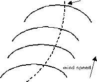 Shaft speed FIGURE 23.43 Shaft power vs shaft speed curves. large number of designs are commercially available, ranging from 50 W to 1.8 MW. The number of blades ranges from one to many in the familiar agriculture windmiU. The best compromise for electricity generation, where high rotational speed aUows use of a smaller and cheaper electric generator, is two or three blades. The mechanical and aerodynamic balance is better for a three-bladed rotor. In smaU wind turbines, three blades are common. Multiblade wind turbines are used for water pumping on farms. Vertical-axis wind turbines (VAWTs) have an axis of rotation that is vertical, and so, unlike the horizontal wind turbines, they can capture winds from any direction without the need to reposition the rotor when the wind direction changes. The vertical-axis wind turbines have also been used in some applications because they do not depend on the direction of the wind. It is relatively easier to extract power. But there are some disadvantages, such as no self-starting system, smaller power coefficient than obtained in the horizontal-axis wind turbines, strong discontinuation of rotations due to periodic changes in the lift force, and stiU-unsatisfactory regulation of power. Based on the pitch control mechanisms, wind turbines can also be classified as fixed-pitch or variable-pitch wind turbines. Different manufacturers offer fixed-pitch and variable-pitch blades. Variable pitch is desirable on large machines because the aerodynamic loads on the blades can be reduced, and when used in fixed-speed operation they can extract more energy. But necessary mechanisms require maintenance, and for smaU machines, instaUed in remote areas, fixed pitch seems more desirable. In some machines, power output regulation involves yawing blades so that they no longer point into the wind. One such system designed in Western Australia has a taU that progressively tilts the blades in a vertical plane so that they present a smaU surface to the wind at high speeds. 23.3.1.2 Types of Wind Generators The three most common electric generators used for isolated wind-power generation are: Dc generators Synchronous generators or permanent-magnet synchronous generators Asynchronous generators The dc generator and field-wound alternators have maintenance problems associated with commutators and brush gear. Schemes based on permanent-magnet alternators and induction generators are receiving close attention because of quah-ties such as ruggedness, low cost, manufacturing simphcity, and low maintenance requirements. Despite many positive features over the conventional synchronous generators, the PMSG has not been used widely [23]. However, the advances in power electronics has made it possible to control the variable-voltage, variable-frequency output of PMSGs. The permanent- magnet machine is generally favored for developing new designs, because of its higher efficiency and the possibUity of a somewhat smaUer diameter. These PMSG machines are now being used with variable-speed wind machines [24]. In the large power system networks, generally the synchronous generators are used. The synchronous generators can supply both active and reactive power, and their reactive power flow can be controlled. The synchronous generators can operate at any power factor. For an induction generator driven by wind turbines, it is a weU-known fact that it can deliver only active power and requires reactive power, although reactive power can be provided from an advanced static var compensator (ASVG). Squirrel-cage induction generators are widely used with fixed-speed wind turbines. In some applications, wound-rotor induction generators have also been used with adequate control schemes for regulating speed by external rotor resistance. This aUows the shape of the torque-slip curve to be controUed to improve the dynamics of the drive train. In the case of PMSG, the converter/inverter can be used to control the variable-voltage-variable-frequency signal of the wind generator at varying wind speed. The converter converts this varying signal to the dc signal, and the output of converter is converted to an ac signal of desired amplitude and frequency. Induction generators are not locked to the frequency of the network. Gyclic torque fluctuations at the wind turbine can be absorbed by a very smaU change in the slip speed. In the case of the capacitor-excited induction generators, they obtain the magnetizing current from capacitors connected across their output terminals [25-27]. 23.3.2 Types of Wind Power Systems Wind power systems can be classified as: Stand-alone Hybrid Grid-connected 23.3.3 Stand-Alone Wind Energy Systems Stand-alone wind energy systems are being used for the following purposes in remote-area power systems: Battery charging Household power supply 23.3.3.1 Battery Charging with Stand-Alone Wind Energy Systems The basic elements of a stand-alone wind energy conversion system are: Wind generator Tower Gharge control system Battery storage Distribution network In a remote-area power supply, an inverter and a diesel generator are more reliable and sophisticated systems. Most smaU isolated wind energy systems use batteries as a storage device to level out mismatch between the availability of the wind and the load requirement. Batteries are a major cost component in an isolated power system. 23.3.3.2 Wind Turbine Charge Controller The basic block diagram of a stand-alone wind generator and battery charging system is shown in Fig. 23.44. The function of the charge controUer is to feed the power from the wind generator to the battery bank in a controUed manner. In the commonly used permanent-magnet generators, this is usually done by using controlled rectifiers [28]. The controUer should be designed to limit the maximum current into the battery, reduce charging current for a high battery state of charge, and maintain a trickle charge during fuU-state-of-charge periods. 23.3.4 Wind-Diesel Hybrid Systems The detaUs of hybrid systems have been covered in Section 23.2.4. Diesel systems without batteries in a remote area are characterized by poor efficiency and high maintenance and fuel costs. The diesel generators must be operated above a certain minimum load level to reduce cylinder wear and tear due to incomplete combustion. It is a common practice to instaU dump loads to dissipate extra energy. More efficient systems can be devised by combining the diesel generator with a battery inverter subsystem and incorporating renewable energy sources, such as wind/solar where appropriate. An integrated hybrid energy system incorporating a diesel generator, wind generator, battery or flywheel storage, and inverter wiU be cost-effective at many sites with an average daily energy demand exceeding 25kWh [29]. These hybrid energy systems can serve as a minigrid as a part of distributed generation rather than extending the grid to the remote rural areas. The heart of the hybrid system is a high-quality sine-wave inverter, which can also be operated in reverse as a battery charger. The system can cope with loads ranging from zero (inverter-only operation) to approximately three times greater capacity (inverter and diesel operating in paraUel). Generator Г Charge controller 1 Permanent Magnet or Capacitor Excited Battery DC load Wind turbine FIGURE 23.44 Block diagram for wind turbine charge controller. A decentrahzed form of generation can be beneficial in a remote-area power supply. Because of the high cost of PV systems and the problems associated with storing electricity over longer periods (such as maintenance difficulties and costs), wind turbines can be a viable alternative in hybrid systems. Systems with battery storage, however, provide better rehabUity. Wind power penetration can be high enough to make a significant impact on the operation of diesel generators. Fiigh wind penetration also poses significant technical problems for the system designer in terms of control and transient stability [30]. In earlier stages of wind-diesel systems, they were instaUed without assessment of system behavior, because of the lack of design tools/software. With the continual research in this area, there is now software avaUable to assist in this process. Wind-diesel technology has now matured because of research and development in this area. Now there is a need to utihze this knowledge in designing cost-effective and reliable hybrid systems [30]. In Western Australia, dynamic modeling of a wind diesel hybrid system has been developed in Curtin/MUERI, supported by the Australian Cooperative Research Centre for Renewable Energy (ACRE) program 23.5.21. 23.3.5 Grid-Connected Wind Energy Systems Wind turbines connected to the grid (weak or strong) are discussed here. Wind-diesel systems have received attention in many remote parts of the world. Remote-area power supphes are characterized by low inertia, low damping, and poor reactive power support. Such weak power systems are more susceptible to sudden changes in network operating conditions [31]. In this weak-grid situation, the significant power fluctuations in the grid would lead to reduced quality of supply to users. This may manifest itself as voltage and frequency variations or spikes in the power supply. These weak grid systems need appropriate storage and control systems to smooth out these fluctuations without sacrificing the peak power tracking capabUity. These systems can have two storage elements. The first is the inertia of rotating mechanical parts, which includes blades, gearbox, and the rotor of the generators. Instead of wind-speed fluctuation causing a large and immediate change in the electrical output of the generator, as in a fixed-speed machine, the fluctuation wiU cause a change in shaft speed and not create a significant change in generator output. The second energy storage element is the smaU battery storage between the dc-dc converter and the inverter. The energy in a gust could be stored temporarily in the battery bank and released during a luU in the wind speed, thus reducing the size of fluctuations. The addition of inverter control would further reduce the fluctuations and increase the total output power. Thus the total output of the wind energy system can be stabihzed or smoothed to track the average wind speed and may not show every gust. The system controUer should track the peak power to keep the output of the wind energy system constant. It should monitor the stator output and adjust the inverter to smooth the total output. The amount of smoothing would depend on the state of charge of the battery. The nominal total output would be adjusted to keep the battery bank state of charge at a reasonable level. In this way, the total wind energy system wiU track the long-term variations in the wind speed without having fluctuations caused by the wind. The storage capacity of the battery bank need only be several minutes to smooth out the gusts in the wind, which can be easily handled by the weak grid. In cases where the weak grid is powered by diesel generators, the conventional wind turbine can cause the diesel engines to operate at low capacity. In case of strong wind apphcations, the fluctuations in the output of the wind energy generator system can be readily absorbed by the grid. The main aim here is to extract the maximum energy from the wind. The basic block layout of such a system [32] is shown in Fig. 23.45. The function of the dc-dc converter wiU be to adjust the torque on the machine and hence ensure by measurement of wind speed and shaft speed that the turbine blades are operating so as to extract optimum power. The purpose of the inverter is to feed the energy gathered by the rotor and dc-dc converter, in the process of peak power tracking, to the grid system. The interaction between the two sections would be tightly controUed so as to minimize or eliminate the need for a battery bank. The control must be fast enough that the inverter output power set point matches the output of the dc-dc converter. For a wound rotor induction machine operating over a two-to-one speed range, the maximum power extracted from the rotor is equal to the power rating of the stator. Thus, the rating of the generator from a traditional point of view is only half that of the wind turbine [32]. Since half the power comes from the stator and half from the rotor, the power electronics of the dc-dc converter and Wind speed Stator Battery
System Controller \ \ \ Grid figure 23.45 System block diagram of grid-connected wind energy system. inverter need to handle only half the total wind-turbine output, and no battery would be required. 23.3.5.1 Soft Starters for Induction Generators When an induction generator is connected to a load, a large inrush current flows. This is something simUar to the direct on-line starting problem of induction machines [24]. It has been observed that the initial time constants of an induction machine are higher when it tries to stabUize initially at the normal operating conditions. There is a need to use some type of soft-starting equipment to start the large induction generators. A simple scheme to achieve this is shown in Fig. 23.46. Two thyristors are connected in each phase, back to back. Initially, when the induction generator is connected, the thyristors are used to control the voltage applied to the stator and to limit the large inrush current. As soon as the generator is fully connected, the bypass switch is used to bypass the soft-starter unit. 23.3.6 Control of Wind Turbines Theory indicates that operation of a wind turbine at fixed tip-speed ratio (Cpjax) ensures enhanced energy capture [33]. Wind energy systems must be designed so that above the rated wind speed, the control system limits the turbine output. In normal operation, medium- to large-scale wind turbines are connected to a large grid. Various wind turbine control pohcies have been studied around the world. Grid-connected wind-turbine generators can be classified as fixed-speed and variable-speed. 23.3.6.1 Fixed-Speed Wind Turbines In case of a fixed-speed wind turbine, synchronous or squirrel-cage induction generators are employed and are characterized by stiff power-train dynamics. The rotational speed of the wind turbine generator in this case is fixed by the grid frequency. The generator is locked to the grid, thereby permitting only smaU deviations of the rotor shaft speed from the nominal value. The speed is very responsive to wind-speed fluctuations. The normal method to smooth the surges caused by the wind is to change the turbine aerodynamic characteristics, either passively by staU regulation or actively by blade-pitch regulation. Wind turbines often are subjected to wind Wmd turbine -t- Induction generator Power distribution System figure 23.46 Soft starting for wind turbine coupled with induction generator. -o о FIGURE 23.47 С /Я curves for different pitch settings. speeds that are very low (below cut-in speed) or high (above rated value). Sometimes they generate below rated power. No pitch regulation is apphed when the wind turbine is operating below rated speed, but pitch control is required when the machine is operating above rated wind speed to minimize the stress. Figure 23.47 shows the effect of blade pitch angle on the torque speed curve at a given wind speed. Blade pitch control is a very effective way of controUing wind turbine speed at high wind speeds, hence limiting the power and torque output of the wind machine. An alternative but cruder control technique is based on airfoil staU [33]. A synchronous link maintaining a fixed turbine speed in combination with an appropriate airfoil can be designed so that, at higher than rated wind speeds, the torque is reduced because of airfoU stall. This method does not require external intervention or complicated hardware, but it captures less energy and has greater blade fatigue. The aims of variable pitch control of medium- and large-scale wind turbines were to help in startup and shut-down operation, to protect against overspeed, and to limit the load on the wind turbine [34]. The turbine is normally operated between the lower and upper limits of wind speed (typically 4.5 to 26 m/s). When the wind speed is too low or too high, the wind turbine is stopped to reduce wear and damage. The wind turbine must be capable of being started and run up to speed in a safe and controlled manner. The aerodynamic characteristics of some turbines are such that they are not self-starting. The required starting torque may be provided by motoring or by changing the pitch angle of the blade [35]. In the case of grid-connected wind turbine system, the rotational speed of the generator is locked to the frequency of the grid. When the generator is directly run by the rotor, the grid acts as an infinite load. When the grid faUs, the load rapidly decreases to zero, causing the turbine rotor to accelerate quickly. Over-speed protection must be provided by rapid braking of the turbine. A simple mechanism of blade pitch-control techniques is shown in Fig. 23.48. rotor speed Wind speed Bade pitch angle Wind Turbine Pmech. Generator -Voltage CXirrent Pitch Actuator
Torque fater FIGURE 23.48 Pitch-control block diagram. In this system, the permanent-magnet generator has been used without any gearbox. Direct connection of generator to the wind turbine requires the generator to have a large number of poles. Both induction generators and wound filed synchronous generators of high pole number require a large diameter for efficient operation. Permanent-magnet synchronous generators allow a smaU pole pitch to be used [36]. The power output, Pmech У turbinc dcpcnds mainly on the wind speed, which dictates the rotational speed of the wind turbine rotor. From the wind speed and the rotational speed of the turbine, the tip speed ratio Я is determined. Based on the computed Я, the power coefficient Cp is inferred. In the control strategy just given, the torque output. Tactual the generator is monitored for a given wind speed and compared with the desired torque. Tactual depending on the load requirement. The generator output torque is passed through the measurement filter. The pitch controUer then infers the modified pitch angle based on the torque error. This modified pitch angle demand and computed Я decide the new Cp, resulting in a modified wind generator power and torque output. The controller will keep adjusting the blade pitch angle until the desired power and torque output are achieved. Some wind-turbine generatora include a gearbox for interfacing the turbine rotor and the generator. The general drive train model [34] for such a system is shown in Fig. 23.49. This system also contains the blade-pitch angle control provision. The drive train converts the input aerodynamic torque on the rotor into torque on the low-speed shaft. This torque is converted to high-speed shaft torque using the gearbox and fluid couphng. The speed of the wind turbine here is low and the gearbox is required to increase the speed so as to drive the generator at the rated rpm, e.g., 1500 rpm. The fluid coupling works as a velocity-in-torque-out device and transfer the torque [34]. The actuator regulates the tip angle based on the control system applied. The control system here is based on a pitch regulation scheme where the blade-pitch angle is adjusted to obtain the desired output power. 23.3.6.2 Variable-Speed Wind Turbines Variable-speed, constant-frequency turbine drive trains are not directly coupled to the grid. The power-conditioning device is used to interface the wind generator to the grid. The output of the wind generator can be variable voltage and variable frequency, which is not suitable for grid integration, and appropriate interfacing is required. The wind turbine rotor in this case is permitted to rotate at any wind speed by the power-generating unit. A number of schemes have been proposed in the past that aUow wind turbines to operate with variable rotor speed while feeding the power to a constant frequency grid. Some of the benefits that have been claimed for variable-speed, constant-frequency wind turbine configuration foUow [32]. Variable-speed operation results in increased energy capture by maintaining the ratio of blade-tip speed to wind speed near the optimum value. By aUowing the wind turbine generator to run at variable speed, the torque can be fixed and the shaft power aUowed to increase. This means that the rated power of the machine can be increased with no structural changes. A variable-speed turbine is capable of absorbing energy in wind gusts as it speeds up and giving back this energy to the system as it slows down. This reduces turbulence-induced stresses and allows capture of a large percentage of the turbulent energy in the wind. More efficient operation can be achieved by avoiding aerodynamic staU over most of the operating range. Progress in power electronics conversion systems has given a major boost to implementing the concept of variable-speed operation. Research studies have shown that the most significant potential advancement for wind turbine technology is in the area of power-electronic-controUed variable-speed operation. There is much research underway in the United States and Europe on developing variable-speed wind turbines as cost-effectively as possible. In the United States, the NASA MOD-0 and MOD-5B were operated as variable-speed wind turbines [32]. Companies in the United States and Enercon (Germany) made machines incorporate a variable-speed feature. An Enercon variable-speed wind machine is already in operation in Denham, Western Austraha. The ability to operate at varying rotor speed effectively adds compliance to the power-train dynamics of the wind turbine. Although many approaches have been suggested for variable-speed wind turbines, they can be grouped into two main classes: (a) discretely variable speed and (b) continuously variable speed [32, 37]. 23.3.6.3 Discretely Variable Speed Systems The discretely variable speed category includes electrical systems where multiple generators are used, either with different numbers of poles or connected to the wind rotor through different gearing ratios. It also includes those generators that can use different number of poles in the stator or can approximate the effect by appropriate switching. Some of the generators in this category are those with consequent poles, dual winding, or pole amplitude modulation. A brief summary of some of these concepts is presented next. 23,3,6,3,1 Pole-Changing Type Induction Generators These generators provide two speeds, a factor of two apart, such as four-pole/eight-pole (1500/750 rpm at a supply frequency of 50 Hz or 1800/900 rpm at 60 Hz). They do this by using one-half of the poles at the higher speed. These machines are commercially available and cost about 50% more than the corresponding single-speed machines. Their main disadvantage, in comparison with other discretely variable machines, is
 Gear box 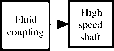 blade Generator
FIGURE 23.49 Block diagram of drive train model. that the 2-to-l speed range is wider than the optimum range for a wind turbine [38]. 23.3.6.3.2 Dual Stator Winding Two Speed Induction Generators These machines have two separate stator windings, only one of which is active at a time. Thus, a variety of speed ranges can be obtained depending on the number of poles in each winding. As in the consequent pole machines, only two speeds may be obtained. These machines are significantly heavier than single-speed machines and their efficiency is less, since one winding is always unused, which leads to increased losses. These machines are commercially available. Their cost is approximately twice that of single-speed machines [38]. 23.3.6.3.3 Multiple Generators This configuration is based on the use of a multiple generator design. In one case, there may simply be two separate generators (as used on many European wind turbines). Another possibility is to have two generators on the same shaft, only one of which is electrically connected at a time. The gearing is arranged such that the generators reach synchronous speed at different turbine rotor speeds. 23.3.6.3.4 Two-Speed Pole-Amplitude Modulated (РАМ) Induction Generator This configuration consists of an induction machine with a single stator, which may have two different operating speeds. It differs from conventional generators only in the winding design. Speed is controUed by switching the connections of the six stator leads. The winding is built in two sections that wiU be in paraUel for one speed and in series for the other. The result is the superposition of one alternating frequency on another. This causes the field to have an effectively different number of poles in the two cases, resulting in two different operating speeds. The efficiency of the РАМ is comparable to that of a single-speed machine. The cost is approximately twice that of conventional induction generators. The use of a discretely variable speed generator wiU result in some of the benefits of continuously variable speed operation, but not aU of them. The main effect wiU be in increased energy productivity, because the wind turbine wiU be able to operate close to its optimum tip speed ratio over a great range of wind speeds than wiU a constant speed machine. On the other hand it wiU perform as a single-speed machine with respect to rapid changes in wind speed (turbulence). Thus it could not be expected to extract the fluctuating energy as effectively from the wind as would the continuously variable speed machine. More importantly, it could not use the inertia of the rotor to absorb torque spikes. Thus, this approach would not result in improved fatigue life of the machine and it could not be an integral part of an optimized design such as one using yaw/speed control or pitch/speed control. 23.3.6.4 Continuously Variable Speed Systems The second main class of systems for variable-speed operation are those that aUow the speed to be varied continuously. For the continuously variable speed wind turbine, there may be more than one control, depending on the desired control action: Mechanical control Combination of electrical/mechanical Electrical Electrical/power electronics control The mechanical methods include hydraulic and variable ratio transmissions. An example of an electrical/mechanical system is one in which the stator of the generator is aUowed to rotate. The aU-electrical category includes high-slip induction generators and the tandem generator. The power electronic category contains a number of possible options. One option is to use a synchronous generator or a wound rotor induction generator, although a conventional induction generator may also be used. The power electronics is used to condition some or aU of the power to a form appropriate to the grid. The power electronics may also be used to rectif) some or aU of the power from the generator, to control the rotational speed of the generator, or to supply reactive power. These systems are discussed below. 23,3,6,4,1 Mechanical Systems Variable-Speed Hydraulic Transmission One method of generating electrical power at a fixed frequency, while aUowing the rotor to turn at variable speed, is the use of a variable-speed hydraulic transmission. In this configuration, a hydraulic system is used in the transfer of the power from the top of the tower to ground level (assuming a horizontal-axis wind turbine). A fixed-displacement hydraulic pump is connected directly to the turbine (or possibly gearbox) shaft. The hydraulic fluid is fed to and from the naceUe via a rotary fluid coupling. At the base of the tower is a variable-displacement hydraulic motor, which is governed to run at constant speed and drive a standard generator. One advantage of this concept is that the electrical equipment can be placed at ground level, making the rest of the machine simpler. For smaUer machines, it may be possible to dispense with a gearbox altogether. On the other hand, there are a number of problems using hydrauhc transmissions in wind turbines. For one thing, pumps and motors of the size needed in wind turbines of greater than about 200 kW are not readily available. Multiples of smaUer units are possible, but this would complicate the design. The life expectancy of many of the parts, especially seals, may weU be less than 5 years. Leakage of hydraulic fluid can be a significant problem, necessitating frequent maintenance. Losses in the hydraulics could also make the overaU system less efficient than conventional electric generation. Experience over many years has not shown great success with wind machines using hydrauhc transmissions. Variable-Ratio Transmission A variable-ratio transmission (VRT) is one in which the gear ratio may be varied continuously within a given range. One type of VRT suggested for wind turbines is using belts and pulleys, such as are used in some industrial drives [32, 39]. These have the advantage of being able to drive a conventional fixed-speed generator, while being driven by a variable-speed turbine rotor. On the other hand, they do not appear to be commercially available in larger sizes, and those that do exist have relatively high losses. 233,6,4,2 Electrical/Mechanical Variable Speed Systems Rotating Stator Induction Generator This system uses a conventional squirrel-cage induction generator whose shaft is driven by a wind turbine through a gearbox [33, 40]. However, the stator is mounted to a support, which aUows bidirectional rotation. This support is in turn driven by a dc machine. The armature of the dc machine is fed from a bidirectional inverter, which is connected to the fixed-frequency ac grid. If the stator support aUowed to turn in the same direction as the wind turbine, the turbine wiU turn faster. Some of the power from the wind turbine wiU be absorbed by the induction generator stator and fed to the grid through the inverter. Conversely, the wind turbine wiU turn more slowly when the stator support is driven in the opposite direction. The amount of current (and thus the torque) delivered to or from the dc machine is determined by a closed-loop control circuit whose feedback signal is driven by a tachometer mounted on the shaft of the dc machine. One of the problems with this system is that the stator shp rings and brushes must be sized to take the fuU power of the generator. They would be subjected to wear and would require maintenance. The dc machine also adds to cost, complexity, and maintenance. 23,3,6,4,3 Electrical Variable-Speed Systems High-Slip Induction Generator This is the simplest variable-speed system, which is accomplished by having a relatively large amount of resistance in the rotor of an induction generator. However, the losses increase with increased rotor resistance. Westwind Turbines in Australia investigated such a scheme on a 30-kW machine in 1989. Tandem Induction Generator A tandem induction generator consists of an induction machine fitted with two magnetically independent stators, one fixed in position and the other able to be rotated, and a single squirrel-cage rotor whose bars extend the length of both stators [32, 41]. Torque control is achieved by physical adjustment of the angular displacement between the two stators, which causes a phase shift between the induced rotor voltages. 23,3,6,4,4 Electrical/Power Electronics The general configuration, shown in Fig. 23.50, consists of the following components: Wind generator Converter Inverter The generator may be dc, synchronous (wound-rotor or permanent-magnet type), squirrel-cage, wound-rotor, or brushless doubly fed induction generator. The input converter is used to convert the variable-voltage, variable-frequency voltage to the dc voltage. This dc voltage is converted into ac of constant voltage and frequency of desired amplitude. The inverter wiU also be used to control the active/reactive power flow from the inverter. In the case of a dc generator, the converter may not be required or when a cycloconverter is used to convert the ac directly from one frequency to another. 23.3.6.5 Generator Options for Variable-Speed Wind Turbines using Power Electronics Power electronics may be applied to three types of generators to facUitate variable-speed operation: Synchronous generators Squirrel-cage induction generators Wound-rotor induction generators 23,3,6,5,1 Synchronous Generator In this configuration, the synchronous generator is aUowed to run at variable speed, producing power of variable voltage and frequency. Control Wind Turbine > Generator С-F---6 Rectifier Inverter л Grid FIGURE 23.50 Grid-connected wind energy system through dc/ac converter. may be facilitated by adjusting an externally supplied field current. The most common type of power conversion uses a bridge rectifier (controUed/uncontroUed), a dc hnk, and inverter as shown in Fig. 23.50. The disadvantages of this configuration include the relatively high cost and maintenance requirements of synchronous generators and the need for the power conversion system to take the full power generated (as opposed to the wound-rotor system). 23.3.6.5.2 Squirrel-Cage Induction Generator Possible architectures for systems using conventional induction generators that have a solid squirrel-cage rotor have many similarities to those with synchronous generators. The main difference is that the induction generator is not inherently self-exciting and it needs a source of reactive power. This could be done by a generator-side self-commutated converter operating in the rectifier mode. A significant advantage of this configuration is the low cost and low maintenance requirements of induction generators. Another advantage of using the self-commu-tated double converter is that it can be on the ground, completely separate from the wind machine. If there is a problem in the converter, it could be switched out of the circuit for repair and the wind machine could continue to run at constant speed. The main disadvantage with this configuration is that, as with the synchronous generator, the power conversion system would have to take the fuU power generated and could be relatively costly compared to some other configurations. There would also be additional complexities associated with the supply of reactive power to the generator. 23.3.6.5.3 Wound-Rotor Induction Generator A wound-rotor induction rotor has three-phase winding on the rotor, accessible to the outside via slip rings. The possible methods of accessing the rotor can have the following configurations: Slip power recovery Use of cycloconverter Rotor resistance chopper control Slip Power Recovery (Static Kramer System) The slip power recovery configuration behaves similarly to a conventional induction generator with very large shp, but in addition energy is recovered from the rotor. The rotor power is first carried out through slip rings, then rectified and passed through a dc hnk to a line-commutated inverter and into the grid. The rest of the power comes directly from the stator as it normally does. A disadvantage with this system is that it can only aUow supersynchronous variable-speed operation. Its possible use in wind power was reported by Smith and Nigim [42]. In this scheme (as shown in Fig. 23.51), the stator is directly connected to the grid. The power converter has been connected to the rotor of the wound-rotor induction generator to obtain the optimum power from the variable-speed wind turbine. The main advantage of this scheme is that the power conditioning unit has to handle only a fraction of the total power so as to obtain fuU control of the generator. This is very important when wind turbine sizes are increasing for grid-connected applications for higher penetration of wind energy, and a smaller converter can be used in this scheme. Cycloconverter (Static Scherbius System) A cycloconverter is a converter that converts ac voltage of one frequency to another frequency without an intermediate dc link. When a cycloconverter is connected to the rotor circuit, sub- and supersynchronous operation variable-speed operation is possible. In supersynchronous operation, this configuration is similar to slip power recovery. In addition, energy may be fed into the rotor, thus aUowing the machine to generate at subsynchro-nous speeds. For that reason, the generator is said to be doubly fed [43]. This system has a limited abUity to control reactive power at the terminals of the generator, although as a whole it is a net consumer of reactive power. On the other hand, if coupled with capacitor excitation, this capability could be useful from the utility point of view. Because of its abUity to rapidly adjust phase angle and magnitude of the terminal voltage, the generator can be resynchronized after a major electrical disturbance without going through a complete stop/start sequence. With some wind turbines, this could be a useful feature. Rotor Resistance Chopper Control A fairly simple scheme for extracting rotor power in the form of heat has been proposed in [44]. 23.3.6.6 Isolated Grid Supply System with Multiple Wind Turbines An isolated grid supply system with a wind park is shown in Fig. 23.52. Two or more wind turbines can be connected to this system. A diesel generator can be connected in paraUel. The converter-connected wind generators wiU work in paraUel and the supervisory control block wiU control the output of these wind generators in conjunction with the diesel generator. This type of decentralized generation can be a better option where high penetration of wind generation is sought. The individual converter wiU control the voltage and frequency of the system. The supervisory control system wiU play an DOIG (Double Wmd output Turbine Induction Generator) Fater Converter Line filter Transformer Grid FIGURE 23.51 Schematic diagram of doubly fed induction generator. Generator Wbd Turbnel DODC Converter DOAC Converter Generator Wild ТшЪпег DCyDC DOAC Converter Converter Dbsel&igne I [ Supervisory control ] [Synchronous J Осасплхя FIGURE 23.52 Schematic diagram of isolated grid system having a wind park. important part in coordination between multiple power generation systems in a remote-area power supply having weak grid. References 1. Georg Hille, Werner Roth, and Heribert Schmidt, Photovoltaic systems, Fraunhofer Institute for Solar Energy Systems, Freiburg, Germany, 1995. 2. OKA Heinrich Wilk, Utility connected photovoltaic systems, contribution to design handbook. Expert meeting Montreux, October 19-21, 1992, International Energy Agency (lEA): Solar Heating and Cooling Program. 3. Stuart R. Wenham, Martin A. Green, and Muriel E. Watt, Applied photovoltaics, Centre for photovoltaic devices and systems, UNSW. 4. N. Ashari, W. W. L. Keerthipala, and C. V. Nayar, A single phase parallel connected Uninterruptible power supply/Demand side management system, PE-275-EC (08-99), IEEE Transactions on Energy Conversion, August 1999. 5. C. V. Nayar, and M. Ashari, Phase power balancing of a diesel generator using a bi-directional PWM inverter, IEEE Power Engineering Review 19 (1999). 6. C. V. Nayar, J. Perahia, S. J. Philips, S. Sadler, and U. Duetchler, Optimized power electronic device for a solar powered centrifugal pump, lournal of the Solar Energy Society of India, SESI lournal 3(2), 87-98 (1993). 7. Ziyad M. Salameh, and Fouad Dagher, The effect of electrical array reconfiguration on the performance of a PV-powered volumetric water pump, IEEE Transactions on Energy Conversion 5 653-658 (1990). 8. C. V. Nayar, S. J. Phillips, and W. L. James, T. L. Pryor, D. Remmer, Novel wind/diesel/battery hybrid system, Solar Energy 51, 65-78 (1993). 9. W. Bower, Merging photovoltaic hardware development with hybrid applications in the U.S.A. Proceedings Solar 93 ANZSES, Fremantle, Western Australia (1993). 10. Ned Mohan, M. Undeland, and W. P. Robbins, Power Electronics, 2nd ed. John Wiley and Sons, Inc. (1995). 11. M. Calais, V. G. Agelidis, M. Meinhardt, Multilevel Converters for single phase grid connected photovoltaic systems - an overview, Solar Energy 66, 325-535 (1999). 12. K. Hirachi, K. Matsumoto, M. Yamamoto, and M. Nakaoka, Improved control implementation of single phase current fed PWM inverter for photovoltaic power generation, Seventh International Conference on Power Electronics and Variable Speed drives (PEVD98). 13. U. Boegli and R. Ulmi, Realisation of a new inverter circuit for direct photovoltaic energy feedback into the pubHc grid, IEEE Transactions on Industry Application, March/April (1986). 14. B. Lindgren, Topology for decentraUsed solar energy inverters with a low voltage A-Bus: EPE99 (European Power Electronics Conference) (1999). 15. Khalid Masoud and Gerard Ledwich, Aspects of grid interfacing: cu-rent and voltage controllers, Proceedings of AUPEC 99, pp 258-263. 16. J. F. Lindsay and M. H. Rashid, Electro-mechanics and Electrical Machinery, Prentice Hall Inc., 1986. 17. Lawrence J. Borle and Michael S. Dymond, Chemmangot V. Nayar, Development and testing of a 20 kW grid interactive photovoltaic power conditioning system in Western Australia, IEEE Transactions on Industry Applications 33, 1-7 (1999). 18. Lawrence J. Borle and C. V. Nayar, Zero average current error controlled power flow for ac-dc power converters, IEEE Transactions on Power Electronics 10, 725-732 (1995). 19. Hari Sharma, Grid integration of photovoltaics, Ph.D. thesis. The University of Newcastle, Austraha (1998). 20. D. Langridge, W. Lawrance, and B. Wichert, Development of a photo-voltaic pumping system using a brushless D.C. motor and helical rotor pump, Solar Energy 56, 151-160 (1996). 21. Donald Paul Hodel, Photovoltaics - Electricity from sunlight, U.S. Department of Energy report, DOE/NBMCE-1075. 22. C. V. Nayar, Small scale wind electricity generation - design criteria, ТЮЕЪ 111-131 (1993). 23. M. A. Rahman, A. M. Osheiba, and T. S. Radwan, Modelling and controller design of an isolated diesel engine permanent magnet synchronous generator, IEEE Proc. on Energy Conversion 11, 324-330 (1996). 24. Godfrey Boyle, Renewable Energy: Power for a Sustainable Future, Oxford University Press, in association with the Open University. 25. J. Arillaga, and N. Watson, Static power conversion from self excited induction generators, Proc. of Institution of Electrical Engineers 125(8), 743-746. 26. C. V. Nayar, J. Perahia, F. Thomas, S. J. Phillips, T. L. Pryor, and W. L. James, Investigation of capacitor excited induction generators and permanent magnet alternators for small scale wind power generation, Renewable Energy 1 381-388 (1991). 27. C. V. Nayar, J. Perahia, and F. Thomas, Small scale wind powered electrical generators, Report no 71, The Minerals and Energy Research Institute of Western Australia, 182 pp. (1992). 28. Bergey Windpower Co., 10 kW Battery charging wind energy generating system, Bergey Windpower Co. report, Oklahoma, USA, 30 pp. (1984). 29. J. H. R. Enslin and F. W. Leuschner, Integrated hybrid energy systems for isolated and semi-isolated users, Proc. of Renewable Energy Potential in Southern African Conference, 1986, UCT, South Africa, September 8-10, pp. 43.1-43.12. 1 ... 54 55 56 57 58 59 60 ... 91 |
||||||||||||||||||||||||||||||||||||||||||||||||||||
|
© 2026 AutoElektrix.ru
Частичное копирование материалов разрешено при условии активной ссылки |