 |
 |
 |
| Главная Журналы Популярное Audi - почему их так назвали? Как появилась марка Bmw? Откуда появился Lexus? Достижения и устремления Mercedes-Benz Первые модели Chevrolet Электромобиль Nissan Leaf |
Главная » Журналы » Metal oxide semiconductor 1 ... 55 56 57 58 59 60 61 ... 91 30. D. G. Infield, Wind diesel systems technology and modelling - a review International Journal of Renewable Energy Engineering 1, 17-27 (1999). 31. Hari Sharma, S. M. Islam, Chem V. Nayar, and Trevor Pryor, Dynamic response of a remote area power system to fluctuating wind speed , Proceedings of IEEE Power Engineering Society (PES 2000) Winter Meeting, CDROM IEEE Catalog No. 00CH37077C (2000). 32. W. L. James, C. V. Nayar, F. Thomas, and M. Dymond, Variable speed asynchronous wind powered generator with dynamic power conditioning, report of Murdoch University Energy Research Institute (MUERI), Australia (1993). 33. L. L. Freris, Wind Energy Conversion Systems, Prentice Hall, 1990. 34. J. Wilkie, W. E. Leithead, and C. Anderson, Modelling of wind turbines by simple models, Wind Engineering 14 247-273 (1990). 35. W. E. Leithead, S. de la Salle, and D. Reardon, Role and objectives of control for wind turbines, lEE Proceedings C 138 (1991). 36. A. L. G. Westlake, J. R. Bumby, and E. Spooner, Damping the power angle oscillations of a permanent magnet synchronous generator with particular reference to wind turbine applications, lEE Proc, Electrical Power Appl 143, 269-280 (1996). 37. J. F. Manwell, J. G. McGowan, and B. H. Bailey, Electri- cal/Mechanical options for variable speed turbines, Solar Energy 46, 41-51 (1991). 38. T. S. Andersen and H. S. Kirschbaum, Multi-speed electrical generator applications in wind turbines, AIAA/SERI Wind Energy Conference Proc, Boulder, CO (1980). 39. J. Van Leuven, An economic comparison of various operating modes for grid connected WECS, Proc. of the Delphi workshop on Wind Energy Applications (1985). 40. R. Carli, Electricity generation at fixed frequency with variable speed WECS, Proc. of European Wind Energy Conference, Rome (1986). 41. J. Perahia and C. V. Nayar, Power controller for a wind-turbine driven tandem induction generator, Electric Machines and Power Systems 19, 599-624 (1991). 42. G. A. Smith and K. A. Nigim, Wind energy recovery by static Scherbius induction generator, lEE Proceedings, Part C, Generation, Transmission and Distribution, 128, 317-324 (1981). 43. T. S. Anderson and P. S. Hughes, Investigation of doubly fed induction machine in variable speed applications, Research report, Westinghouse Electric Corporation (1983). 44. C. V. Nayar and J. H. Bundell, Output power controller for a wind-driven induction generator, IEEE Transactions on Aerospace and Electronic Systems, AES-23, 388-401 (1987). HVDC Transmission Vijay K. Sood, Ph.D. Expertise-Equipements Electriques Hydro-Quebec (IREQ) 1800 Lionel Boulet Varennes, Quebec Canada J3X ISl 24.1 Introduction...................................................................................... 575 24.1.1 Comparison of ac and dc Transmission 24.1.2 Evaluation of Reliability and Availability Costs 24.1.3 Applications of dc Transmission 24.1.4 Types of HVDC Systems 24.2 Main Components of HVDC Converter Station...................................... 580 24.2.1 Converter Unit 24.2.2 Converter Transformer 24.2.3 Filters 24.2.4 Reactive Power Source 24.2.5 DC Smoothing Reactor 24.2.6 DC Switchgear 24.2.7 DC Cables 24.3 Analysis of Converter Bridge................................................................ 583 24.4 Controls and Protection...................................................................... 583 24.4.1 Basics of Control for a Two-Terminal dc Link 24.4.2 Control Implementation 24.4.3 Control Loops 24.4.4 Hierarchy of dc Controls 24.4.5 Monitoring of Signals 24.4.6 Protection Against Overcurrents 24.4.7 Protection against Overvoltages 24.5 MTDC Operation............................................................................... 589 24.5.1 Series Tap 24.5.2 Parallel Tap 24.5.3 Control of MTDC Systems 24.6 Applications....................................................................................... 591 24.6.1 HVDC Interconnection at Gurun (Malaysia) 24.7 Modern Trends................................................................................... 592 24.7.1 Converter Station Design of the 2000s 24.8 HVDC System Simulation Techniques.................................................... 595 24.8.1 Dc Simulators and TNAS 24.8.2 Digital Computer Analysis 24.9 Conclusion........................................................................................ 596 References......................................................................................... 597 24.1 Introduction High-voltage direct current (HVDC) transmission [1-3] is a major user of power electronics technology. HVDC technology first made its mark in the early undersea cable interconnections of Gotland (1954) and Sardinia (1967), and then in longdistance transmission with the Pacific Intertie (1970) and Nelson River (1973) schemes using mercury-arc valves. A significant milestone development occurred in 1972 with the first back-to-back (BB) asynchronous interconnection at Eel River between Quebec and New Brunswick; this instaUation also marked the introduction of thyristor valves to the technology and replaced the earlier mercury-arc valves. To understand the rapid growth of dc transmission (Table 24.1) [4] in the past 50 years, it is first necessary to compare it to conventional ac transmission. 24.1.1 Comparison of ac and dc Transmission Making a planning selection between ac and dc transmission is based on an evaluation of transmission costs, technical considerations, and the reliability/availability offered by the two transmission alternatives. 24.1.1.1 Evaluation of Transmission Costs The cost of a transmission hne comprises the capital investment required for the actual infrastructure [i.e., right-of-way (RoW), towers, conductors, insulators, and terminal equipment] and costs incurred for operational requirements (i.e. losses). Assuming similar insulation requirements for peak voltage levels for both ac and dc lines, a dc hne can carry as much power with two conductors (having positive/negative polarities with respect to ground) as an ac hne with three TABLE 24.1 Listing of HVDC installations
A, ASEA; B, Brown Boveri; C, General Electric; D, Toshiba; E, Hitachi; F, Russian; G, Siemens; H, CGEE Alsthom; I, GEC (Former Eng. Elec); J, HVDC W.G. (AEG, BBC, Siemens); K, Independent; AB, ABB Brown Boveri; JV, Joint Venture (GE and ASEA). Retired from service. 2 VG.s replaced with thyristors in 1977. 2 VG.s in Pole 1 replaced with thyristors by GEC in 1991. Back-to-back HVDC system. 50 MW thyristor tap. Up-rated w/thyristor valves. conductors of the same size. Therefore, for a given power level, a dc line requires smaller RoW, simpler and cheaper towers, and reduced conductor and insulator costs. As an example. Fig. 24.1 shows the comparative case of ac and dc systems carrying 2000 MW. Right-of-Way Typical DC and AC Transmission Line Structures for aoDrox. 2000 MW 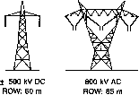 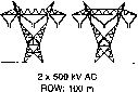 With the dc option, since there are only two conductors (with the same current capacity as three ac conductors), the power transmission losses are also reduced to about two-thirds of those of the comparable ac system. The absence of skin effect with dc is also beneficial in reducing power losses marginally, and the dielectric losses in the case of power cables are also very much less for dc transmission. Corona effects tend to be less significant for dc than for ac conductors. The other factors that influence hne costs are the costs of compensation and terminal equipment. Dc lines do not require reactive power compensation but the terminal equipment costs are increased because of the presence of converters and filters. Figure 24.2 shows the variation of costs of transmission with distance for ac and dc transmission. Ac tends to be more economical than dc for distances less than the breakeven distance but is more expensive for longer distances. The breakeven distances can vary from 500 to 800 km in overhead lines depending on the per-unit line costs. With a cable system, this breakeven distance approaches 50 km. costs 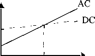 breakeven distance distance FIGURE 24.2 Comparison of ac-dc lines. 24.1.1.2 Evaluation of Technical Considerations Because of its fast controllability, dc transmission has full control over transmitted power and the ability to enhance transient and dynamic stability in associated ac networks. It can also hmit fault currents in the dc lines. Furthermore, dc transmission overcomes some of the following problems associated with ac transmission. 24.1.1.2.1 Stability Limits The power transfer in an ac line is dependent on the angle difference between the voltage phasors at the two line ends. For a given power transfer level, this angle increases with distance. The maximum power transfer is limited by the considerations of steady-state and transient stability. The power-carrying capability of an ac line is inversely proportional to transmission distance, whereas the power-carrying ability of dc lines is unaffected by the distance of transmission. 24.1.1.2.2 Voltage Control Voltage control in ac lines is complicated by line charging and voltage drops. The voltage profile in an ac line is relatively flat only for a fixed level of power transfer corresponding to its surge impedance loading (SIL). The voltage profile varies with the line loading. For constant voltage at the hne ends, the midpoint voltage is reduced for line loadings higher than SIL and increased for loadings less than SIL. The maintenance of constant voltage at the two ends requires reactive power control as the line loading is increased. The reactive power requirements increase with hne length. Although dc converter stations require reactive power related to the power transmitted, the dc line itself does not require any reactive power. The steady-state charging currents in ac cables pose serious problems and make the breakeven distance for cable transmission around 50 km. 24.1.1.2.3 Line Compensation Line compensation is necessary for long-distance ac transmission to overcome the problems of hne charging and stability hmitations. An increase in power transfer and voltage control is possible through the use of shunt inductors, series capacitors, static var compensators (SVCs) and, lately, the new-generation static compensators (STATCOMs). In the case of dc hues, such compensation is not needed. 24.1.1.2.4 Problems of ac Interconnection The interconnection of two power systems through ac ties requires the automatic generation controllers of both systems to be coordinated using tie line power and frequency signals. Even with coordinated control of interconnected systems, the operation of ac ties can be problematic because of (i) the presence of large power oscillations that can lead to frequent tripping, (ii) an increase in fault level, and (iii) transmission of disturbances from one system to the other. The fast controUability of power flow in dc lines eliminates all of the above problems. Furthermore, the asynchronous interconnection of two power systems can only be achieved with the use of dc links. 24.1.1.2.5 Ground Impedance In ac transmission, the existence of ground (zero sequence) current cannot be permitted in steady state because of the high magnitude of ground impedance, which wiU not only affect efficient power transfer, but also result in telephonic interference. The ground impedance is neghgible for dc currents, and a dc link can operate using one conductor with ground return (monopolar operation). The ground return is objectionable only when buried metalhc structures (such as pipes) are present and are subject to corrosion with dc current flow. It is to be noted that even while operating in the monopolar mode, the ac network feeding the dc converter station operates with balanced voltages and currents. Hence, single-pole operation of dc transmission systems is possible for an extended period, whereas in ac transmission, single-phase operation (or any unbalanced operation) is not feasible for more than a second. 24.1.1.2.6 Problems of dc Transmission The application of dc transmission is limited by factors such as the foUowing: 1. High cost of conversion equipment 2. Inability to use transformers to alter voltage levels 3. Generation of harmonics 4. Requirement of reactive power 5. Complexity of controls Over the years, there have been significant advances in dc technology, which have tried to overcome the disadvantages just listed above, except for item 2. These are: 1. Increase in the ratings of a thyristor ceU that makes up a valve 2. Modular construction of thyristor valves 3. Twelve-pulse operation of converters 4. Use of force-commutation 5. Apphcation of digital electronics and fiber optics in the control of converters Some of the preceding advances have resulted in improving the rehability and reduction of conversion costs in dc systems. 24.1.2 Evaluation of Reliability and Availability Costs Statistics on the rehabihty of HVDC hnks are maintained by CIGRE and IEEE Working Groups. The rehabihty of dc hnks has been very good and is comparable with that of ac systems. The availability of dc hnks is quoted in the upper 90%. 24.1.3 Applications of dc Transmission Because of their costs and special nature, most apphcations of dc transmission generally faU into one of the following four categories: Underground or underwater cables. In the case of long cable connections over the breakeven distance of about 40-50 km, the dc cable transmission system has a marked advantage over ac cable connections. Examples of this type of application were the Gotland (1954) and Sardinia (1967) schemes. The recent development of voltage-source converters (VSC) and the use of rugged polymer dc cables, with the so-called HVDC Light option, is being increasingly considered. An example of this type of application is the 180-MW Directlink connection (2000) in Australia. Long-distance bulk power transmission. Bulk power transmission over long distances is an application ideally suited for dc transmission and is more economical than ac transmission whenever the breakeven distance is exceeded. Examples of this type of apphcation abound from the earher Pacific Intertie to the recent links in China and India. The breakeven distance is being effectively decreased by the reduced cost of new compact converter stations made possible by the recent advances in power electronics (discussed in a later section). Asynchronous interconnection of ac systems. In terms of an asynchronous interconnection between two ac systems, the dc option reigns supreme. There are many instances of BB connections where two ac networks have been tied together for the overaU advantage to both ac systems. With recent advances in control techniques, these interconnections are being increasingly made at weak ac systems. The growth of BB interconnections is best iUustrated with the example of North America, where the four main independent power systems are interconnected with 12 BB links. In the future, it is anticipated that these BB connections wiU also be made with VSCs offering the possibUity of fuU four-quadrant operation and the total control of active/ reactive power coupled with the minimal generation of harmonics. Stabilization of power flows in integrated power systems. In large interconnected systems, power flow in ac ties (particularly under disturbance conditions) can be uncontrolled and lead to overloads and stabUity problems, thus endangering system security. Strategically placed dc lines can overcome this problem because of the fast controUabUity of dc power and provide much needed damping and timely overload capabUity. The planning of dc transmission in such applications requires detaUed study to evaluate the benefits. Examples are the IPP link in the United States and the Chandrapur-Padghe link in India. Presently the number of dc hnes in a power grid is very smaU compared to the number of ac lines. This indicates that dc transmission is justified only for specific applications. Although advances in technology and introduction of multi-terminal dc (MTDC) systems are expected to increase the scope of application of dc transmission, it is not anticipated that a dc power grid wiU replace the ac grid in the future. There are two major reasons for this. First, the control and protection of MTDC systems is complex and the inability of voltage transformation in dc networks imposes economic penalties. Second, the advances in power electronics technology have resulted in the improvement of the performance of ac transmissions using FACTS devices, for instance through introduction of static var systems and static phase shifters. 24.1.4 Types of HVDC Systems Three types of dc links are considered in HVDC applications. 24.1.4.1 Monopolar Link A monopolar link (Fig. 24.3a) has one conductor and uses either ground and/or sea return. A metaUic return can also be used where concerns for harmonic interference and/or corrosion exist. In applications with dc cables (i.e., HVDC Light), a cable return is used. Since the corona effects in a dc hne are substantially less with negative polarity of the conductor as compared to positive polarity, a monopolar hnk is normally operated with negative polarity. 24.1.4.2 Bipolar Link A bipolar link (Fig. 24.3b) has two conductors, one positive and the other negative. Each terminal has two sets of converters of equal rating, in series on the dc side. The junction between the two sets of converters is grounded at one or both ends by the use of a short electrode line. Since both poles operate with equal currents under normal operation, there is zero ground current flowing under these conditions. Monopolar operation can also be used in the first stages of the development of a bipolar link. Alternatively, under faulty converter conditions, one dc line may be temporarily used as a metaUic return with the use of suitable switching. 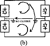 О О FIGURE 24.3 Types of HVDC links: (a) monopolar link, (b) bipolar link, and (c) homopolar dc link. 24.1.4.3 Homopolar Link In this type of link (Fig. 24.3c) two conductors having the same polarity (usually negative) can be operated with ground or metallic return. Because of the undesirabihty of operating a dc link with ground return, bipolar links are mostly used. A homopolar link has the advantage of reduced insulation costs, but the disadvantages of earth return outweigh the advantages. 24.2 Main Components of HVDC Converter Station The major components of an HVDC transmission system are the converter stations at the ends of the transmission system. In a typical two-terminal transmission system, both a rectifier and an inverter are required. The role of the two stations can be reversed, as controls are usually available for both functions at the terminals. The major components of a typical 12-pulse bipolar HVDC converter station (Fig. 24.4) are discussed next. design of valves is based on a modular concept where each module contains a limited number of series-connected thyristor levels. The valves can be packaged as a single-valve, double-valve, or quadruple-valve arrangement. Converter transformers connected in star/star and star/delta arrangements to form a 12-pulse pair feed the converter. Air, oil, water or Freon may be used to cool the valves. However, cooling using deionized water is more modern and considered efficient and reliable. The ratings of a valve group are limited more by the permissible short-circuit currents than by the steady-state load requirements. Valve firing signals are generated in the converter control at ground potential and are transmitted to each thyristor in the valve through a fiber-optic light-guide system. The light signal received at the thyristor level is converted to an electrical signal using gate-drive amplifiers with pulse transformers. Recent trends in the industry indicate that direct optical firing of the valves with ITT thyristors is also feasible. The valves are protected using snubber circuits, protective firing, and gapless surge arrestors. 24.2.1 Converter Unit This usually consists of two three-phase converter bridges connected in series to form a 12-pulse converter unit. The 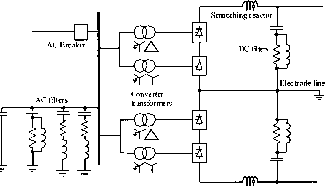 FIGURE 24.4 Typical HVDC converter station equipment. 24.2.1.1 Thyristor Valves Many individual thyristors are connected in series to build up an HVDC valve. To distribute the off-state valve voltage uniformly across each thyristor level and protect the valve from di/dt and dv/dt stresses, special snubber circuits are used across each thyristor level (Fig. 24.5). The snubber circuit is composed of the foUowing components: A saturating reactor is used to protect the valve from di/dt stresses during turn-on. The saturating reactor offers a high inductance at low current and a low inductance at high currents. A dc grading resistor RG distributes the direct voltage across the different thyristor levels. It is also used as a voltage divider to measure the thyristor level voltage. RC snubber circuits are used to damp out voltage osciUations varying from power frequency to a few kUo-hertz.  Saturating reactor Breakover diode -H-1 Gate Electronics i ? j 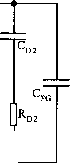 DATABACK FIRING Optical fibres FIGURE 24.5 Electrical circuit of the thyristor level [2]. A capacitive grading circuit Cp is used to protect the thyristor level from voltage osciUations at a much higher frequency. A firing pulse sent via a fiber-optic cable from the valve base electronics (VBE) unit at earth potential triggers a thyristor on. A gate electronic unit (GEU), which receives its power from the RC snubber circuit during the valves off period, amplifies the fiber-optic signal. The GEU can also effect the protective firing of the thyristor independent of the central control unit. This is achieved by a breakover diode (BOD) via a current-limiting resistor that triggers the thyristor when the forward voltage threatens to exceed the rated voltage for the thyristor. This may arise in a case when some thyristors may block forward voltage while others may not. It is normal to include some extra redundant thyristor levels to allow the valve to remain in service after the failure of some thyristors. A metal-oxide surge arrestor is also used across each valve for overvoltage protection. The thyristors produce considerable heat loss, typically 30 to 40W/cm (or over IMW for a typical quadruple valve), and so an efficient cooling system is essential. 24.2.2 Converter Transformer The converter transformer (Fig. 24.6) can have different configurations: (i) three-phase, two-winding, (ii) single-phase, three-winding, and (iii) single-phase, two-winding. The valve-side windings are connected in star and delta with neutral point ungrounded. On the ac side, the transformers are connected in paraUel with the neutral grounded. The FIGURE 24.6 Spare converter transformer in the switchyard of an HVDC station. leakage impedance of the transformer (typical values vary between 15 and 18%) is chosen to limit the short-circuit current through any valve. The converter transformers are designed to withstand dc voltage stresses and increased eddy-current losses due to harmonic currents. One problem that can arise is due to the dc magnetization of the core due to unsymmetrical firing of valves. 24.2.3 Filters Because of the generation of characteristic and noncharacter-istic harmonics by the converter, it is necessary to provide suitable filters on the ac-dc sides of the converter to improve the power quality and meet telephonic and other requirements. Generally, three types of filters are used for this purpose: ac, dc, and high-frequency (RF/PLC) filters. 24.2.3.1 AC Filters AC filters (Fig. 24.7) are passive circuits used to provide low-impedance shunt paths for ac harmonic currents. Both tuned and damped filter arrangements are used. In a typical 12-pulse station, filters at the 11th and 13th harmonics are required as tuned filters. Damped filters (normally tuned to the 23rd harmonic) are required for the higher harmonics. In recent years, filters such as C-type fihers have also been used since they provide more economic designs. Double- or even triple-tuned filters exist to reduce the cost of the filter (see the example system discussed in Section 24.6). The avaUabUity of cost-effective active ac filters wiU change the scenario in the future. 24.2.3.2 DC Filters These are similar to ac filters and are used for the filtering of dc harmonics. Usually a damped filter at the 24th harmonic is FIGURE 24.7 Installation of an ac filter in the switchyard. Utilized. Modern practice is to use active dc filters (see also the apphcation example system presented later). Active dc filters are increasingly being used for efficiency and space-saving purposes. 24.2.3.3 High-Frequency (RF/PLC) Filters These are connected between the converter transformer and the station ac bus to suppress any high-frequency currents. Sometimes such filters are provided on the high-voltage dc bus connected between the dc filter and dc line and also on the neutral side. 24.2.4 Reactive Power Source Converter stations consume reactive power that is dependent on the active power loading (typically about 50% to 60% of the active power). The ac filters provide part of this reactive power requirement. In addition, shunt (switched) capacitors and static var systems are also used. 24.2.5 DC Smoothing Reactor A sufficiently large series reactor is used on the dc side of the converter to smooth the dc current and for converter protection from line surges. The reactor (Fig. 24.8) is usually designed as a linear reactor and may be connected on the hne side, on the neutral side, or at an intermediate location. Typical values of the smoothing reactor are in the 300-600 mH range for long-distance transmission and about 30 mH for a BB connection. 24.2.6 DC Switchgear This is usually modified ac equipment and used to interrupt only smaU dc currents (i.e., employed as disconnecting switches). Dc breakers or metaUic return transfer breakers (MRTB) are used, if required, for the interruption of rated load currents. In addition to the equipment described above, ac switchgear and associated equipment for protection and measurement are also part of the converter station. 24.2.7 DC Cables In contrast to the use of ac cables for transmission, dc cables do not have a requirement for continuous charging current. Hence the length limit of about 50 km does not apply. Moreover, dc voltage gives less aging and hence a longer lifetime for the cable. The new design of HVDC Light cables from ABB are based on extruded polymeric insulating material instead of classic paper-oil insulation, which has a tendency to leak. Because of their rugged mechanical design, flexibility, and low FIGURE 24.8 Installation of an air-cooled smoothing reactor. 1 ... 55 56 57 58 59 60 61 ... 91 |
|
© 2026 AutoElektrix.ru
Частичное копирование материалов разрешено при условии активной ссылки |