 |
 |
 |
| Главная Журналы Популярное Audi - почему их так назвали? Как появилась марка Bmw? Откуда появился Lexus? Достижения и устремления Mercedes-Benz Первые модели Chevrolet Электромобиль Nissan Leaf |
Главная » Журналы » Metal oxide semiconductor 1 ... 56 57 58 59 60 61 62 ... 91 weight, polymer cables can be installed underground cheaply with a plowing technique, or in submarine apphcations can be laid in very deep waters and on rough sea-bottoms. Since dc cables are operated in bipolar mode, one cable with positive polarity and one cable with negative polarity, very limited magnetic fields result fi-om the transmission. HVDC Light cables have successfully achieved operation at a stress of 20kV/mm. 24.3 Analysis of Converter Bridges To consider the theoretical analysis of a conventional six-pulse bridge (Fig. 24.9), the following assumptions are made: The dc current /j is considered constant Valves are ideal switches The ac system is strong (infinite) Because of the leakage impedance of the converter transformer, commutation from one valve to the next is not instantaneous. An overlap period is necessary and, depending on the leakage, two, three, or four valves may conduct at any time. In the general case, with a typical value of converter transformer leakage impedance of about 13-18%, either two or three valves conduct at any one time. The analysis of the bridge gives the foUowing dc output voltages: For a rectifier: dr = dor cosa-i.r-d (24.1) where Vjj. = 3/n a/2 Vll = (/)Lr For an inverter: There are two options possible, depending on choice of either the advance angle P or extinction angle у as the control variable. -V = V r coslRrk (24.2) -di = -Vdoi-cos7 + i,i./d (24.3) where Vjj. and are the dc voltage at the rectifier and inverter, respectively -У Vjoj. and Vjoi are the open-circuit dc voltage at the rectifier and inverter, respectively Vdor = (3/7r)*1.414*VLLr Vdoi = (3/7r)*1.414*VLLi Vllf LLi the line-line voltages at the rectifier and inverter, respectively Rj. and R are the equivalent commutation resistance at the rectifier and inverter, respectively Lj. and are the leakage inductances of the converter transformer at rectifier and inverter, respectively R = (3/)*w*4r R = (3/)*w*L,i /j is dc current a is delay angle j] is advance angle at the inverter = % - a) у is extinction angle at the inverter {y = % - a - fi) fl is overlap angle at the inverter 24.4 Controls and Protection In a typical two-terminal dc link connecting two ac systems (Fig. 24.10), the primary functions of the dc controls are as foUows: Control power flow between the terminals Protect the equipment against the current/voltage stresses caused by faults StabUize the attached ac systems against any operational mode of the dc link The dc terminals each have their own local controUers. A centralized dispatch center wiU communicate a power order to one of the terminals that wiU act as a Master ControUer and has the responsibility to coordinate the control functions of the dc link. Besides the primary functions, it is desirable that the dc controls have the foUowing features: Limit the maximum dc current. Because of the limited thermal inertia of the thyristor valves to sustain over-currents, the maximum dc current is usually limited to less than 1.2 pu for a limited period of time. ACSysteml Local Cbntrols IVbster Controls DCSystei Teleocrns ACSystem2 Dispatch centre Maintain a maximum dc voltage for transmission. This reduces the transmission losses and permits optimization of the valve rating and insulation. Minimize reactive power consumption. This implies that the converters must operate at a low firing angle. A typical converter wiU consume reactive power between 50 and 60% of its MW rating. This amount of reactive power supply can cost about 15% of the station cost and comprise about 10% of the power loss. The desired features of the dc controls are as follows: Limit maximum dc current: Since the thermal inertia of the converter valves is quite low, it is desirable to limit the dc current to prevent failure in the valves. Maintain maximum dc voltage for transmission purposes to minimize losses in the dc line and converter valves. Keep the ac reactive power demand low at either converter terminal. This imphes that the operating angles at the converters must be kept low. Additional benefits of doing this are to reduce the snubber losses in the valves and reduce the generation of harmonics. Prevent commutation failures at the inverter station and hence improve the stabihty of power transmission. Other features, i.e., the control of frequency in an isolated ac system or enhancement of power system stability, are also desirable. In addition to these desired features, the dc controls wiU have to cope with the steady-state and dynamic requirements of the dc link, as shown in Table 24.2. TABLE 24.2 Requirements of the dc link Steady-State Requirements Dynamic Requirements Limit the generation of non-characteristic harmonics Maintain the accuracy of the controlled variable, i.e., dc current and/or constant extinction angle Cope with the normal variations in the ac system impedance due to topology changes Step changes in dc current or power flow Startup and fault-induced transients Reversal of power flow Variation in frequency of attached ac system 24.4.1 Basics of Control for a Two-Terminal dc Link From converter theory, the relationship between the dc voltage Vj and dc current /j is given as in Eqs. (24.1)-(24.3). These three characteristics represent straight lines on the Vj-/j plane. Notice that Eq. (24.2), i.e., the beta characteristic, has a positive slope, while Eq. (24.3), i.e., the gamma characteristic, has a negative slope. The choice of the control strategy for a typical two-terminal dc link is made according to conditions in Table 24.3. Condition 1 imphes the use of the rectifier in constant-current control mode; condition 3 implies the use of the inverter in constant extinction angle (CEA) control mode. Other control modes may be used to enhance the power transmission during contingency conditions depending on applications. This control strategy is illustrated in Fig. 24.11. The rectifier characteristic is composed of two control modes: alpha-min (line AB) and constant-current (line ВС). The alpha-min mode of control at the rectifier is imposed by the natural characteristics of the rectifier ac system and the ability of the valves to operate at alpha equal to zero, i.e., in the hmit the rectifier acts a diode rectifier. However, since a minimum positive voltage is desired before firing of the valves to ensure conduction, an alpha-min limit of about 2-5° is imposed. The inverter characteristic is composed of two modes: gamma-min (line PQ) and constant-current (line QR). The operating point for the dc link is defined by the crossover point X of the two characteristics. In addition, a constant-current characteristic is also used at the inverter. However, the current demanded by the inverter /j is usually less than the current demanded by the rectifier I by the current margin А/ that is typically about 0.1 pu. The current margin is selected to be large enough that the rectifier and inverter constant-current modes do not interact because of any current harmonics which may be superimposed on the dc current. This control strategy is termed the current margin method. The advantage of this control strategy becomes evident if there is a voltage decrease at the rectifier ac bus. The operating point then moves to point Y. Consequently, the current transmitted wiU be reduced to 0.9 pu of its previous value and voltage control will shift to the rectifier. However, the TABLE 24.3 Choice of control strategy for two-terminal dc link Condition # Desirable Features Reason Control Implementation Limit the maximum dc current, Employ the maximum dc voltage, Reduce the incidence of commutation failures Reduce reactive power consumption at the converters For the protection of valves For reducing power transmission losses For stability purposes For voltage regulation and economic reasons Use constant current control at the rectifier Use constant voltage control at the inverter Use minimum extinction angle control at inverter Use minimum firing angles
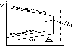 Idi Idr > Id (a) (b) FIGURE 24.11 Static V-I characteristic for a two-terminal link: (a) unmodified and (b) modified. power transmission wiU be largely maintained near to 90% of its original value. The control strategy usually employs the foUowing other modifications to improve the behavior during system disturbances: 1. At the rectifier: Voltage-dependent current limit (VDCL). This modification is made to limit the dc current as a function of either the dc voltage or, in some cases, the ac voltage. This modification assists the dc link to recover from faults. Variants of this type of VDCL do exist. In one variant, the modification is a simple fixed value instead of a sloped line. /j-min limit. This limitation (typically 0.2-0.3 pu) is to ensure a minimum dc current to avoid the possibUity of dc current extinction caused by the valve current dropping below the hold-on current of the thyristors, an eventuality that could arise transiently because of harmonics superimposed on the low value of the dc current. The resultant current chopping would cause high overvoltages to appear on the valves. The magnitude of /j-min is affected by the size of the smoothing reactor employed. 2. At the inverter: Alpha-min limit at inverter. The inverter is usually not permitted to operate inadvertently in the rectifier region, i.e., a power reversal occurring because of, say, an inadvertent current margin sign change. To ensure this, an alpha-minimum limit in inverter mode of about 100-110° is imposed. Current error region. When the inverter operates into a weak ac system, the slope of the CEA control mode characteristic is quite steep and may cause multiple crossover points with the rectifier charac- teristic. To avoid this possibUity, the inverter CEA characteristic is usually modified into either a constant beta characteristic or constant voltage characteristic within the current error region. 24.4.2 Control Implementation 24.4.2.1 Historical Background The equidistant pulse firing control systems used in modern FiVDC control systems were developed in the mid-1960s [5,6]; although improvements have occurred in their implementation since then, such as the use of microprocessor-based equipment, their fundamental phUosophy has not changed much. The control techniques described in [5,6] are of the pulse-frequency control (PFC) type as opposed to the now-out-of-favor pulse-phase control (PPC) type. AU these controls use an independent voltage-controUed osciUator (VCO) to decouple the direct coupling between the firing pulses and the commutation voltage, V. This decoupling was necessary to eliminate the possibUity of harmonic instabU-ity detected in the converter operation when the ac system capacity became nearer to the power transmission capacity of the FiVDC hnk, i.e., with the use of weak ac systems. Another advantage of the equidistant firing pulse controls was the elimination of noncharacteristic harmonics during steady-state operation. This was a prevalent feature during the use of the earlier individual phase control (IPC) system where the firing pulses were directly coupled to the commutation vohage, V,om- 24.4.2.2 Firing Angle Control To control the firing angle of a converter, it is necessary to synchronize the firing pulses emanating from the ring counter to the ac commutation voltage, which has a frequency of 60 Fiz in steady state. Fiowever, it was noted quite early on (early 1960s) that the commutation voltage (system) is not constant either in frequency or amphtude during a perturbed state. However, it is the frequency that is of primary concern for the synchronization of firing pulses. For strong ac systems, the frequency is relatively constant and distortion free to be acceptable for most converter-type applications. But, as converter connections to weak ac systems became required more often than not, it was necessary to devise a scheme for synchronization purposes that would be decoupled from the commutation voltage frequency for durations when there were perturbations occurring on the ac system. The most obvious method is to utilize an independent osciUator at 60 Hz that can be synchronously locked to the ac commutation voltage frequency. This osciUator would then provide the (phase) reference for the generation of firing pulses to the ring counter during the perturbation periods, and would use the steady-state periods for locking in step with the system frequency. The advantage of this independent osciUator would be to provide an ideal (immunized and clean) sinusoid for synchronizing and timing purposes. There are two possibihties for this independent osciUator: Fixed-frequency operation Variable-frequency operation Use of a fixed-frequency osciUator (although feasible and caUed a pulse-phase control osciUator) is not recommended, since it is known that the system frequency does drift between, say, 55-65 Hz because of the rotating machines used to generate electricity. Therefore, it is necessary to use a variable-frequency oscillator (called a pulse-frequency control osciUator) with a locking range of between, say, 50 and 70 Hz and a center frequency of 60 Hz. This osciUator would then need to track the variations in the system frequency, and a control loop of some sort would be used for this tracking feature; this control loop would have its own gain and time parameters for steady-state accuracy and dynamic performance requirements. The control loop for frequency-tracking purposes would also need to consider the mode of operation for the dc link. The method widely adopted for dc link operation is the so-caUed current margin method. 24.4.3 Control Loops Control loops are required to track the following variables: 1. The ordered current 1. at the rectifier and the inverter 2. The ordered extinction angle (y) at the inverter 24.4.3.1 Current Control Loops In conventional HVDC systems, a PI regulator is used (Fig. 24.12) for the rectifier current controller. The rectifier plant system is inherently nonlinear and has the relationship given >K/(l+sT) VCO- Fling Counte FIGURE 24.12 Control loop for the rectifier. in Eq. (24.1). For constant /j and for smaU changes in a, we have AVd/Aa = -VdorSina (24.4) It is obvious from Eq. (24.4) that the maximum gain (AVj/Aa) occurs when a = 90°. Thus the control loop must be stabUized for this operation point, resulting in slower dynamic properties at normal operation with a within the range 12-18°. Attempts have been made to hnearize this gain and have met with some hmited success. However, in practical terms, it is not always possible to have the dc link operating with the rectifier at 90° because of harmonic generation and other protection elements coming into operation also. Therefore, optimizing the gains of the PI regulator can be quite arduous and take a long time. For this reason, the controllers are often pretested in a physical simulator environment to obtain appropriate settings. Final (often very limited) adjustments are then made on site. Other problems with the use of a PI regulator include the foUowing: It is mostly used with fixed gains, although some possibUity for gain scheduling exists. It is difficult to select optimal gains, and even then they are optimal over a limited range only. Since the plant system is varying continually, the PI controUer is not optimal. A simUar current control loop is used at the inverter (Fig. 24.13). Since the inverter also has a gamma controller, the selection between these two controUers is made via a MINIMUM SELECT block. Moreover, in order to bias the inverter current controUer off, a current margin signal А/ is subtracted from the current reference 4. received from the rectifier via a communication hnk. K/(l + sT) Irorn g3n iTH cxuTtTolIcr о -H vool-► Ring Counter MINIMUM LECT DOCT FIGURE 24.13 Current controller at the inverter. 24,4,3,1,1 Telecommunication Requirements As discussed earlier, the rectifier and inverter current orders must be coordinated to maintain a current margin of about 10% between the two terminals at aU times; otherwise, there is a risk of loss of margin and the dc voltage could run down. Although it is possible to use slow voice communication between the two terminals, and maintain this margin, the advantage of fast control action possible with converters may be lost for protection purposes. For maintaining the margin during dynamic conditions, it is prudent to raise the current order at the rectifier first followed by the inverter; in terms of reducing the current order, it is necessary to reduce at the inverter first and then at the rectifier. 24.4.3.2 Gamma Control Loop At the inverter end, there are two known methods for a gamma control loop. The two variants are different only in the method of determining the extinction angle: Predictive method for the indication of extinction angle (gamma) Direct method for actual measurement of extinction angle (gamma) In either case, a delay of one cycle occurs from the indication of actual gamma and the reaction of the controller to this measurement. Since the avoidance of a commutation failure often takes precedence at the inverter, it is normal to use the minimum value of gamma measured for the six- or twelve-inverter valves for the converter(s). 24,4,3,2,1 Predictive Method of Measuring Gamma The predictive measurement tries to maintain the commutation voltage-time area after commutation larger than a specified minimum value. Since the gamma prediction is only approximate, the method is corrected by a slow feedback loop that calculates the error between the predicted value and actual value of gamma (one cycle later) and feeds it back. The predictor calculates continuously, by a triangular approximation, the total available voltage-time area that remains after commutation is finished. Since an estimate of the overlap angle is necessary, it is derived from a weU-known fact in converter theory that the overlap commutation voltage-time area is directly proportional to direct current and the leakage impedance (assumed constant and known) value of the converter transformer. The prediction process is inherently of an individual phase firing character. If no further measure were taken, each valve would fire on the minimum margin condition. To counteract this undesired property, a special firing symmetrizer is used; when one valve has fired on the minimum margin angle, the following two or five valves fire equidistantly. (The choice of either two or five symmetrized valves is mainly a stability question). 24,4,3,2,2 Direct Method of Measuring Gamma In this method, the gamma measurement is derived from a measurement of the actual valve voltage. Waveforms of the gamma measuring circuit are shown in Fig. 24.14. An internal timing waveform, consisting of a ramp function of fixed slope, is generated after being initiated from the instant of anode current zero. This value corresponds to a direct voltage proportional to the last value of gamma. From the gamma values of aU (either 6 or 12) valves, the smaUest value is selected to produce the indication of measured gamma for use with the feedback regulator (Fig. 24.15). This value is compared to a gamma-ref value and a PI regulator defines the dynamic properties for the controller. Inherently, this method has an individual phase control characteristic. One version of this type of control implementation overcomes this problem by using a symmetrizer for generating equidistant firing pulses. The 12-pulse circuit generates 12 gamma measurements; the minimum gamma value is selected and then used to derive the control voltage for the firing pulse generator with symmetrical pulses. 24.4.4 Hierarchy of dc Controls Since FiVDC controls are hierarchical in nature, they can be subdivided into blocks, which follow the major modules of a converter station (Fig. 24.16). The main control blocks are as foUows: 1. The bipole (master) controUer is usually located at one end of the dc hnk and receives its power order from a centralized system dispatch center. The bipole controller derives a current order for the pole controUer using a local measurement of either ac or dc voltage. Other inputs may also be used by the bipole controUer, such as frequency control for damping or modulation purposes. A communication to the remote terminal firing pulse, valve 3 anode current, valve 1 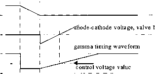 I I I Yref +  K/(l + sT) from current controller Ring Counter MIN SELECT select! valve voltages FIGURE 24.15 Gamma feedback controller. of the dc link is also necessary to coordinate the current references to the link. 2. The pole controUer then derives an alpha order for the next level. This alpha order is sent to both the positive and negative poles of the bipole. 3. The valve group controUers generate the firing pulses for the converter valves. Controls also receive measurements of dc current, dc voltage, and ac current into the converter transformer. These measurements assist in the rapid alteration of firing angle for protection of the valves during perturbations. A slow loop for control of tap changer position as a function of alpha is also avaUable at this level. 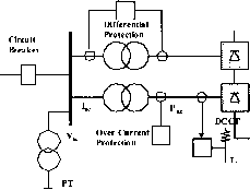 Valve Group 1 Protection TDCVT Pole Differential Protection FIGURE 24.17 Monitoring points for the protection circuits. 24.4.5 Monitoring of Signals As described earher, monitoring of the following signals is necessary for the controls (Fig. 24.17) to perform their functions and assist in the protection of the converter equipment: Vj, /j: Dc voltage and dc current, respectively ac- current on line-side and converter-side of the converter transformer V: Ac voltage at the ac filter bus Dispatoh Centre Bipole Cortroner I ItoiemDte Ыро1е , Ible Cbntrols IpuJses Valve Gkoup Controls firing I pulses Hierarchy of controllers FIGURE 24.16 Hierarchy of controllers. 24.4.6 Protection Against Overcurrents Faults and disturbances can be caused by either malfunctioning equipment or insulation failures due to hghtning and poUution. First, these faults need to be detected with the help of monitored signals. Second, the equipment must be protected by control or switching actions. Since dc controls can react within one cycle, control action is used to protect equipment against overcurrent and overvoltage stresses and minimize loss of transmission. In a converter station, the valves are the most critical (and most expensive) equipment that need to be protected rapidly because of their limited thermal inertia. The basic types of faults that the station can experience are: Current extinction (CE). CE can occur if the valve current drops below the holding current of the thyristor. This can happen at low current operation accompanied by a transient leading to current extinction. Because of the phenomenon of current chopping of an inductive current, severe overvoltages may result. The size of the smoothing reactor and the rectifier I setting help to minimize the occurrence of CE. Commutation failure (CF) or misfire. In line-commutated converters, the successful commutation of a valve requires that the extinction angle 7-nominal be maintained more than the minimum value of the extinction angle y-min. Note that y-nominal = 180 - a - . The overlap angle is a function of the commutation voltage and the dc current. Hence, a decrease in commutation voltage or an increase in dc current can cause an increase in , resulting in a decrease in 7. If 7 < 7-min, a CF may result. In this case, the outgoing valve wiU continue to conduct current, and when the incoming valve is fired in sequence, a short circuit of the bridge wiU occur. A missing firing pulse can also lead to a misfire (at a rectifier) or a CF (at an inverter). The effects of a single misfire are similar to those of a single CF. Usually a single CF is self-clearing, and no special control actions are necessary. However, a multiple CF can lead to the injection of ac voltages into the dc system. Control action may be necessary in this case. The detection of a CF is based on the differential comparison of dc current and the ac currents on the valve side of the converter transformer. During a CF, the two valves in an arm of the bridge are conducting. Therefore, the ac current goes to zero while the dc current continues to flow. Protection features employed to counteract the impact of a CF are indicated in Table 24.4. Short circuits: internal or dc line. An internal bridge fault is rare as the valve haU is completely enclosed and is air-conditioned. However, a bushing can fail, or valve-cooling water may leak, resulting in a short circuit. The ac breaker may have to be tripped to protect against bridge faults. The protection features employed to counteract the impact of short circuits are indicated in Table 24.4. The fast-acting HVDC controls (which operate within one cycle) are used to regulate the dc current for protection of the valves against ac and dc faults. The basic protection (Fig. 24.17) is provided by the VGP differential protection, which compares the rectified current on the valve side of the converter transformer with the dc current measured on the line side of the soothing reactor. This method is apphed because of its selectivity, made possible by the high impedances of the smoothing reactor and converter transformer. The OCP is used as a backup protection in case of malfunction in the VGP. The level of overcurrent is set higher than the differential protection. The pole differential protection (PDP) is used to detect ground faults, including faults in the neutral bus. 24.4.7 Protection against Overvoltages The typical arrangement of metal-oxide surge arrestors for protecting equipment in a converter pole is shown in Fig. 24.18. In general, the ac bus arrestors hmit overvoltages entering from the ac bus; similarly, the dc arrestor limits overvoltages entering the converter from the dc line. The ac and dc filters have their respective arrestors also. Critical components such as the valves have their own arrestors placed close to these components. The protective firing of a valve is used as a backup protection for overvoltages in the forward direction. Owing to their varied duty, these arrestors are rated accordingly for the location used. For instance, the converter arrestor for the upper bridge is subjected to higher energy dissipation than that for the lower bridge. Since the evaluation of insulation coordination is quite complex, detailed studies are often required with dc simulators to design an appropriate insulation coordination strategy. 24.5 MTDC Operation Most HVDC transmission systems are two-terminal systems. A multiterminal dc system (MTDC) has more than two terminals, and there are two existing instaUations of this type. There are two possible ways of tapping power from an HVDC hnk, i.e., with series or paraUel taps. 24.5.1 Series Tap A monopolar version of a three-terminal series dc link is shown in Fig. 24.19. The system is grounded at only one suitable location. In a series dc system, the dc current is set by one terminal and is common to aU terminals; the other TABLE 24.4 Protection against overcurrents
DC reactor arrestor dq Kne arrestor 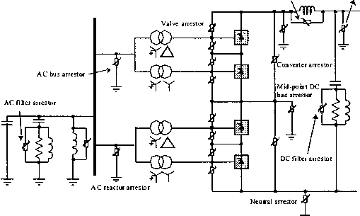 FIGURE 24.18 Typical arrangement of surge arrestors for a converter pole. -t>i- FIGURE 24.19 Series tap. terminals are operated at a constant delay angle for a rectifier and constant extinction angle for inverter operation with the help of transformer tap changers. Power reversal at a station is achieved by reversing the dc voltage with angle control. No practical instaUation of this type exists in the world at present. From an evaluation of ratings and costs for series taps, it is not practical for the series tap to exceed 20% of the rating for a major terminal in the MTDC system. system, the removal of one segment wiU not interrupt power flow, provided the remaining links are capable of carrying the required power. Power reversal in a paraUel system wiU require mechanical switching of the links, as the dc voltage cannot be reversed. From an evaluation of ratings and costs for paraUel taps, it is not practical for the paraUel tap to be less than 20% of the rating for a major terminal in the MTDC system. There are two existing instaUations of paraUel taps in the world. The first is the Sardinia-Corsica-Italy link where a 50-MW parallel tap at Corsica is used. Since the principal terminals are rated at 200 MW, a commutation faUure at Corsica can result in very high overcurrents (typically 7pu); for this reason, large smoothing reactors (2.5 H) are used in this link. The second instaUation is the Quebec-New Hampshire 2000-MW link where a paraUel tap is used at Nicolet. Since the rating of Nicolet is at 1800 MW, the size of the smoothing reactors was kept to a modest size. 24.5.2 Parallel Tap A monopolar version of a three-terminal paraUel dc hnk is shown in Fig. 24.20. In a paraUel MTDC system, the system voltage is common to aU terminals. There are two variants possible for a paraUel MTDC system: radial or mesh. In a radial system, disconnection of one segment of the system wiU interrupt power from one or more terminals. In a mesh FIGURE 24.20 Parallel tap: (a) radial type and (b) mesh type. 24.5.3 Control of MTDC Systems Although several control methods exist for controUing MTDC systems, the most widely utUized method is the so-caUed current margin method that is an extension of the control method used for two-terminal dc systems. In this method, the voltage setting terminal (VST) operates at the angle hmit (minimum alpha or minimum gamma) whUe the remaining terminals are controUing their respective currents. The control law that is used sets the current reference at the voltage setting terminal according to (24.5) where А/ is known as the current margin. The terminal with the lowest voltage ceUing acts as the VST. An example of the control strategy is shown in Fig. 24.21 for a three-terminal dc system with one rectifier REC and two inverters, INVl at 40% and INV2 at 60% rating. The RECl and INV2 terminals are maintained in current control, and INVl is the VST oerating in CEA mode. Because of the requirement to maintain current margin for the MTDC system at aU times, a centralized current controUer, known as the current reference balancer (CRB) (Fig. 24.22), is required. With this technique, reliable two-way telecommunication links are required for current reference coordination purposes. The current orders, irefi~ref3 the terminals must satisfy the control law according to Eq. (24.5). The weighting factors (Ki, and x3) and limits are selected as a function of the relative ratings of the terminals. A RECl V INVl V4 INV2 i<-Ai FIGURE 24.21 Current margin method of control for MTDC system. LIMITERS I refl I ref2 re В Weighting Factors -►-Ire IrefS Hi gh Gain Ampli fi er Л- 24.6 Applications 24.6.1 HVDC Interconnection at Gurun (Malaysia) The 300/600-MW HVDC interconnection between Malaysia and ThaUand (Fig. 24.23) is a major first step in implementing electric power network interconnections in the ASEAN region. It is jointly undertaken by two utUities, Tenaga Nasional Berhad (TNB) of Malaysia and Electricity Generating Authority of ThaUand (EGAT). This wiU be the first HVDC project for both these utUities. The HVDC interconnection consists of a 110-km HVDC line (85 km owned by TNB, and 25 km owned by EGAT) with the dc converter stations at Gurun on the Malaysian side and Khlong Ngae on the ThaUand side. The scheme is scheduled for commercial operation in July 2000. The interconnection wiU provide a range of diverse benefits: Spinning reserve sharing Economic power exchange - commercial transactions Emergency assistance to either ac system Damping of ac system osciUations Reactive power support (voltage control) Deferment of generation plant-up 24.6.1.1 Power Transmission Capacity The converter station is presently constructed for monopolar operation for power transfer of 300 MW in both directions with provisions for future extensions to a bipole configuration giving a total power-transfer capabUity of 600 MW. The HVDC line is constructed with two pole conductors to cater for the second 300 MW pole. FuU-length neutral conductors are used instead of ground electrodes because of high land costs and inherently high values of soU resistivity. The monopole is rated for a continuous power of 300 MW (300 kV, 1000 A) at the dc terminal of the rectifier station. In addition, there is a 10-minute overload capabUity of up to 450 MW that may be utilized once per day when all redundant cooling equipment is in service. The HVDC interconnection scheme is capable of continuous operation at a reduced dc voltage of 210 kV (70%) over the whole load range up to the rated dc current of 1000 A with aU redundant cooling equipment in service. 24.6.1.2 Performance Requirements A high degree of energy avaUabUity was a major design objective. Guaranteed targets for both stations are: Energy availabUity: Forced energy unavailabUity: Forced outage rates: >99.5% <0.43% <5.4 outages per year Malaysia 275 kV TNB 2x60 MVA Tuned to 11/13/27 harmonics Thailand 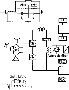 230 kV 2x42 MVA Trr-AT 1x84 MVA Tuned to 12/24/36 harmonics
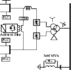 FIGURE 24.23 One-hne diagram of HVDC interconnection between Malaysia and Thailand. 24.6.1.3 Major Technical Features The station incorporates the latest state-of-the-art technology in power electronics and control equipment: A fully decentralized control and protection system Active dc filter technology Hybrid dc current shunt measuring devices Triple-tuned ac filter 24.6.1.4 Technical Information See Fig. 24.23. 24.7 Modem Trends 24.7.1 Converter Station Design of the 2000s The 1500-MW, ib500-kV Riband-Delhi HVDC transmission system (commissioned in 1991) serves as an example of a typical design of the last decade. Its major design aspects were the following: Stations employ water-cooled valves of indoor design with the valves arranged as three quadruple valves suspended from the ceiling of the valve hall. Converter transformers are one-phase, three-winding units situated close to the valve hall with their bushings protruding into the valve hall. Ac filtering is done with conventional, passive, double-tuned and high-pass units employing internally fused capacitors and air-cored reactors; these filters are mechanically switched for reactive power control. Dc filtering is done with conventional, passive units employing a split smoothing reactor consisting of both an oil-filled reactor and an air-cored reactor. DCCT measurement is based on a zero-flux principle. Control and protection hardware is located in a control room in the service building in between the two valve halls. The controls still employ some analog parts, particularly for the protection circuits. The controls were duplicated with an automatic switchover to hot stand-by for reliability reasons. This design was done in the 1980s to meet the requirements of the day for increased reliability and performance requirements, i.e., availability, reduced losses, higher overload capability, etc. However, these requirements led to increased costs for the system. The next generation equipment is now being spearheaded by a desire to reduce costs and make HVDC as competitive as ac transmission. This is being facilitated by the major developments of the past decade that have taken place in power 1 ... 56 57 58 59 60 61 62 ... 91 |
||||||||||||||||||||||||||||||||||||||||||||||||||||||||||||||||||||||
|
© 2026 AutoElektrix.ru
Частичное копирование материалов разрешено при условии активной ссылки |