 |
 |
 |
| Главная Журналы Популярное Audi - почему их так назвали? Как появилась марка Bmw? Откуда появился Lexus? Достижения и устремления Mercedes-Benz Первые модели Chevrolet Электромобиль Nissan Leaf |
Главная » Журналы » Metal oxide semiconductor 1 ... 57 58 59 60 61 62 63 ... 91 electronics. Therefore, the following will influence the next generation HVDC equipment. 24.7.1.1 Thyristor Development HVDC thyristors are now available with a diameter of 150 mm at a rating of 8-9 kV and power-handling capacity of 1500 kW, which wiU lead to a dramatic decrease in the number of series-connected components for a valve, with consequential cost reductions and improvement in reliability. The development of the light-triggered thyristor (LTT) (Figs. 24.24 and 24.25) is likely to eliminate the electronic unit (with their high number of electronic components) for generating the firing pulses for the thyristor (Fig. 24.26). The additional functional requirements of monitoring and protection of the device are being incorporated also. FIGURE 24.24 Silicon wafer and construction of the LTT. The light guides appear in the bottom right-hand corner of the photo. FIGURE 24.25 Cross section of the LTT with the light pipe entry. Electrical triggered Light triggered Gate Electronics Unit Optical fibre Optical Pulse Generator and Control Electronics  Both of the preceding developments present the possibility of achieving compact valves that can be packaged for outdoor construction, thereby reducing the overaU cost and reliability of the station. 24.7.1.2 Higher dc Transmission Voltages For long-distance transmission, there is a tendency to use a high voltage to minimize the losses. The typical transmission voltage has been ±500 kV, although the Itaipu project in BrazU uses 600 kV. The transmission voltage has to be balanced against the cost of insulation. The industry is considering raising the voltage to ±800 kV. 24.7.1.3 Controls It is now possible to operate an HVDC scheme into an extremely weak ac system, even with short-circuit capacity down to unity. Using programmable DSPs has resulted in a compact and modular design that is low cost; furthermore, the number of control cubicles has decreased by a factor of 10 times in the past decade. Now aU control functions are implemented on digital platforms. The controls are fully integrated, having monitoring, control, and protection features. The design incorporates self-diagnostic and supervisory characteristics. The controls are optically coupled to the control room for rehable operation. Redundancy and duplication of controls results in very high reliability and availabUity of the equipment. 24.7.1.4 Outdoor Valves The introduction of air-insulated, outdoor valves wiU reduce the costly requirement for a valve haU. The use of a modular, compact design, which wiU be preassembled in the manufacturing plant, wiU save instaUation time and provide for a flexible station layout. This design has been feasible because of development of a composite insulator for dc applications, which is used as a communications channel for fiber optics, cooling water, and ventUation air between the valve unit and ground. 24.7.1.5 Active dc Filters This development, made possible by advances in power electronics and microprocessors, has resulted in a more efficient dc filter operating over a wide spectrum of frequencies and provides a compact design (Fig. 24.27). 24.7.1.6 Ac Filters Conventional ac filters used passive components for tuning out certain harmonic frequencies. Because of the variations in frequency and capacitance, physical aging and thermal characteristics of these tuned filters, the quality factors for the filters were typically about 100-125, which means that the filters could not be too sharply tuned for efficient harmonic FIGURE 24.27 Compact outdoor container with an active dc filter. FIGURE 24.28 Malaysia. Installation of triple-tuned filter at the Gurun Station in filtering. The advent of electronically tunable inductors based on the transductor principle means that the Q-factors can now approach the natural one of the inductor. This will lead to a much more enhanced filtering capacity. (See Fig. 24.28). 24.7.1.7 Ac-dc Current Measurements The new optical current transducers utilize a precision shunt at high potential. A small optical-fiber link between ground and high potential is utilized, resulting in a lower probability of a flashover. The optical power link transfers power to high potential for use in electronics equipment. The optical data link transfers data to ground potential. This transducer results in high rehability, compact design, and efficient measurement (Fig. 24.29). 24.7.1.8 New Topologies Two new topological changes to the converter design will have a great impact on future designs. 1. Series-compensated commutation. There are two variants to this topology: the capacitor commutated FIGURE 24.29 The optical current transducer. converter (CCC) and the controlled series capacitor converter (CSCC). Essentially, the behavior of the two variants is very similar. The insertion of a capacitor in series with the converter transformer results in a major reduction in the commutation impedance of the converter, resulting in a reduction in the reactive power requirement of the converter. The increase in the size of the series capacitor can even result in the operation at leading power factor if so desired. However, the negative impact of lower commutation impedance results in additional stresses on the valves and transformers and additional cost imphcations. The first CCC back-to-back converter station (2 x 550 MW) has been put into service at Garabi, on the Brazilian side of the Uruguay River. The system interconnects the electrical systems of Argentina and Brazil. 2. Voltage-source converters (VSC). The use of self-commutation with the new generation devices (i.e., GTOs and IGBTs) has resulted in the topology of a voltage-source converter (VSC) as opposed to the conventional converter using ordinary thyristors and current-source converter (CSC) topology. The VSC, being self-commutated, can control active/reactive power, and with PWM techniques, control harmonic generation as well. The switching losses and ratings of available devices presently limit the application of such circuits. The ongoing advances in power electronic devices are expected to have a major impact on the application of this type of converter on HVDC transmission. New application areas particularly in distribution systems are being actively investigated with this topology. Table 24.5 provides a list of the HVDC links in operation using this technique. One major difficulty in using the VSC is the threat posed to the valves from a short circuit on the dc hne, unlike the CSC, TABLE 24.5 Applications of HVDC light technology
where the valves are inherently protected against short-circuit currents by the presence of the smoothing reactor. For this reason, VSC applications are almost always used with dc cables where the dc line short-circuit risk is greatly reduced. 24.7.1.9 Compact Station Layout The advances discussed previously have resulted in marked improvement of the footprint requirement of the compact station of the year 2000, which has about 30% of the space requirement of the comparable FiVDC station designed in the past decade (Fig. 24.30) [7]. 24.8 DC System Simulation Techniques Modern FiVDC systems incorporate complex control and protection equipment. The testing and optimization of these equipment require powerful tools that are capable of modeling aU facets of the system and have the flexibility to do the evaluation in a rapid, effective, and cost-efficient manner. 24.8.1 Dc Simulators and TNAs For decades, this has been achieved with the aid of physical power system simulators or transient network analyzers (TNAs) [8]. These incorporate scaled physical models of all power-system elements [three-phase ac network lines/cables, sources as emf behind reactances, model circuit breakers for precisely timed ac system disturbances, transformers (system and convertor transformers with capacity to model saturation characteristics), filter capacitors, reactors, resistors, arrestors, and machines]. Until the 1970s, these were built with analog components. Fiowever, with the developments in microprocessors, it is now feasible to utilize totally digital simulators operating in realtime for even the most complex FiVDC system studies. The operating scale of most simulators is in rt r Tr rm r mmut t с t r  Tu d P F tr Outd r V V Sm th g r ct r  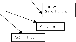 the range 20-100 V dc, 0.2-1.0 A ac and at a power frequency of 50 or 60 Hz. The stray capacitance and inductance are, however, not normally represented, since the simulator is primarily used to assess control system behavior and temporary overvoltages of frequencies below 1000 Hz. Because of the developments of flexible ac transmission systems (FACTS) apphcation, most modern simulators now include scaled models of HVDC converters, static compensators, and other thyristor-controlled equipment. The controls of these equipments are usually capable of realistic performance during transients such as ac faults and commutation failure. The limited availability of adequate models of some of the system elements restricts the scope of the studies that can be completed entirely by means of the simulator. Because of the scaling problems, losses in the simulator may be disproportionately high and need to be partly compensated by electronic circuits (negative resistances) to simulate appropriate damping of overvoltages and other phenomena. 24.9 Conclusion 24.8.2 Digital Computer Analysis The main type of program employed for studies is an electromagnetic transient program (EMTP), which solves sets of differential equations by step-by-step integration methods. The digital program must allow for modeling of both the linear and nonlinear components (single- and three-phase) and of the topological changes caused, for example, by valve firing or by circuit-breaker operation. Detailed modeling of the converter control system is necessary depending on the type of study. The main advantage of digital studies is the possibility of correct representation of the damping present in the system. This feature permits more accurate evaluation of the nature and rate of decay of transient voltages following their peak levels in the initial few cycles, and also a more realistic assessment of the peak current and total energy absorption of the surge arrestors. The digital program also allows modeling of stray inductance and capacitance and can be used to cover a wider frequency range of transients than the dc simulator. The main disadvantage of the digital studies is the lack of adequate representation of commutation failure phenomena with the use of power electronic converters. However, with the increasing capacity of computers, this is likely to be overcome in the future. The models used in the simulators and digital programs depend on the assumptions made and on the proper understanding of the component and system characteristics; therefore, they require care in their usage to avoid unrealistic results in inexperienced hands. HVDC technology is now mature, reliable, and accepted all over the world. From its modest beginning in the 1950s, the technology has advanced considerably and maintained its leading-edge image. The encroaching technology of flexible ac transmission systems (FACTS) has learned and gained from the technological enhancements made initially by HVDC systems. FACTS technology may challenge some of the traditional roles for HVDC applications, since the deregulation of the electrical utility business will open up the market for increased interconnection of networks. HVDC transmission has unique characteristics that will provide it with new opportunities. Although the traditional applications of HVDC transmission will be maintained for bulk power transmission in places such as China, India, South America and Africa, the increasing desire for the exploitation of renewable resources will provide both a challenge and an opportunity for innovative solutions in the following applications: Connection of small dispersed generators to the grid Alternatives to local generation Feeding to urban city centers Acknowledgments The author pays tribute to the many pioneers whose vision of HVDC transmission has led to the rapid evolution of the power industry. It is not possible here to name all of them individually. A number of photographs of equipment are included in this chapter, and I thank the suppliers (Mr. P. Lips of Siemens and Mr. R. L. Vaughan from ABB) for their valued assistance. I also thank my wife Vinay for her considerable assistance in the preparation of this manuscript. List of Abbreviations
References 1. E. W. Kimbark, Direct Current Transmission - Vol 7, Wiley Inter-science, 1971. 2. J. Arrillaga, High Voltage Direct Current Transmission, 2nd ed., The Institution of Electrical Engineers, 1998. 3. K. R. Padiyar, HVDC Power Transmission Systems - Technology and System Interactions, John Wiley & Sons, 1990. 4. HVDC Projects Listing, prepared by IEEE DC and Flexible AC Transmission Subcommittee, D. Melvold. 5. J. Ainsworth, The phase-locked oscillator - A new control system for controlled static converters, IEEE Trans. Power Apparatus and Systems VAS-%7, 859-865 (1968). 6. Ekstrom and G. Liss, A refined HVDC control system, IEEE Trans, on Power Apparatus and Systems PAS-89, 723-732 (1970). 7. L. Carlsson, G. Asplund, H. Bjorklund, and H. Stomberg, Recent and future trends in HVDC converter station design, lEE 2nd International Conference on Advances in Power System Control, Operation and Management, Dec. 1993, Hong Kong, pp. 221-226. 8. C. Gagnon, V. K. Sood, J. Belanger, A. Vallee, M. Toupin, R Mercier, and M. Tetreault, Hydro-Quebec power system simulator, IEEE Canadian Review, No. 19, pp. 6-9, Spring-Summer (1994). Multilevel Converters and VAR Compensation Azeddine Draou, Ph.D. Mustapha Benghanem, Ph.D. Ali Tahri, Ph.D. University of Sciences and Technology of Or an, B.P. 29013 Oran-USTO a Oran, Algeria 25Л Introduction...................................................................................... 599 25.2 Reactive Power Phenomena and their Compensation............................... 600 25.2.1 Power Factor Correction 25.2.2 Voltage Regulation 25.2.3 Load Balancing 25.2.4 Classical Solutions for Compensating the Reactive Power 25.3 Modehng and Analysis of an Advanced Static VAR Compensator............... 603 25.3.1 Main Operating Principles of the ASVC 25.3.2 Modeling of the ASVC System 25.3.3 The ASVC Behavior in Steady State 25.3.4 ASVC Behavior in Transient State 25.3.5 Controller Design 25.3.6 Proposed Control Block Diagram 25.3.7 Conclusion 25.4 Static VAR Compensator for the Improvement of Stability of a Turbo Alternator.......................................................................................... 611 25.4.1 Mathematical Model of the Network ASVC 25.4.2 Proposed Control Strategy 25.4.3 Simulation Results 25.4.4 Conclusion 25.5 Multilevel Inverters............................................................................. 614 25.5.1 Different Structures of the Multilevel Inverters 25.5.2 Conclusion 25.6 The Fiarmonics Elimination Method for a Three-Level Inverter................. 617 25.6.1 PWM Control for Harmonics Elimination 25.6.2 Simulation Results Using PSPICE 25.6.3 Simulated Results of the Programmed PWM Control 25.6.4 Conclusion 25.7 Three-Level ASVC Structure Connected to the Network........................... 620 25.7.1 Operating Principles 25.7.2 Mathematical Model of the ASVC 25.7.3 Controller Design 25.7.4 Simulation Results 25.7.5 Conclusion References......................................................................................... 625 25.1 Introduction Reactive power has no real physical meaning, but is recognized as an essential factor in the design and good operation of power systems. Real and reactive power on a transmission line in an integrated network is governed by the line impedance, voltage magnitudes, the angle difference at the line ends, and the role the line plays in maintaining network stability under dynamic contingencies. Power transfer in most integrated transmission systems is constrained by transient stability, voltage stability, and/or power stabihty. Reactive power (VAR) compensation or control is an essential part in a power system to minimize power transmission losses, to maximize power transmission capability, and to maintain the supply voltage. It is increasingly becoming one of the most economic and effective solutions to both traditional and new problems in power transmissions systems. It is a weU-established practice to use reactive power compensation to control the magnitude of the voltage at a particular bus bar in any electric power system. In the past, synchronous condensers, mechanically switched capacitors and inductors, and saturated reactors have been applied to control the system voltage in this manner [1, 2]. Since the late 1960s, thyristor-controUed reactor (TCR) devices together with fixed capacitors (PCs) or thyristor-switched capacitor (TSCs) have been used to inject or absorb reactive power [3, 4]. Series compensation is the control of the equivalent line impedance of a transmission hne. The induction of external components (either capacitive or inductive) is used to change the apparent reactance of the hne. A controllable series compensator such as the thyristor-controlled series compensation (TCSC) has been developed to change the apparent impedance of a hne by either inductive or capacitive compensation, facilitating active power transfer control. The thyristors control the conduction period of the reactor to vary the overall effective Z of the circuit. The TCSC suffers from the disadvantage that it generates low-order harmonic components into the power system. TCSCs are usually connected in series to conventional line series capacitors. They may consist of one or several identical modules. Each module has a small thyristor-controlled reactor in parallel to the segment series capacitor. Although the TCSC is primarily used for regulating the power flow, though varying its effective reactance inserted in series with the transmission line, it may also be used for voltage stabilization. In this case, the o/p reads terminal voltage within a tight band. Voltage source converters using GTO thyristor have been developed to operate as static VAR compensators [5-7]. These are known as ASVCs. Such converters may resemble the operation of synchronous condensers, but in a static manner. For these devices, a converter transformer is always needed to complement the function of the P.E. switches to perform system VAR compensation and may also be used to connect the device to the HV bus. The converter supplies reactive power to the network by increasing the synthesized inverter o/p voltage. Similarly, the ASVC absorbs VARs from the network by reducing the o/p voltage below the network voltage, i.e., no large power components such as capacitor banks or reactors are used. Only a small capacitor is employed to provide the required reference voltage level to the inverter. In contrast to the TCR/FC or TCR/TSC schemes, bulky and experimental passive elements are not required. The possibility of PWM voltage source converters with high switching frequency for reactive power compensation has also been reported [8, 9]. However, the high-switching-frequency operation of GTOs is not available. In order to apply large-scale reactive power compensation, new svc systems with low-switching-frequency PWM operation have been reported [10-12]. The conventional GTO inverters have dc link voltage limitations of about 2kV. Hence, the series connections of the existing GTO thyristors have been essential in realizing high voltage, about 4 kV. So there has been great interest in the multilevel level inverter topology, which can overcome series connection problems. The multilevel level inverters are able to generate multiple level outputs line to line voltage without output transformers or reactors, i.e., the harmonics components of the phase voltage are fewer than those of the conventional two-level inverter at the same switching frequency. Each alternative has its technical and economical advantages, hmitations, and drawbacks, and it is the scope of this article to provide a thorough comparison of the various ahernatives. 25.2 Reactive Power Phenomena and Their Compensation In an ideal electroenergetic system, the voltage and frequency in the various points of power distribution must be constant, presenting only the fundamental component (harmonics contents nil) and a near-unity power factor. In particular, these parameters must be independent of the size and characteristics of the consumer loads; this can be obtained only if these loads are equipped with reactive power compensators to make the network independent from probable changes that appear in the distribution points [1]. Compensation of the loads is one of the techniques for the controlling reactive power, so to improve the quality of the energy in the ac transmission lines; this technique is generally used for the compensation of individual or a group of loads. This has three essential objectives: Power factor correction Improvement of the voltage regulation Load balancing It is noted that power factor correction and load balancing are desired even when the supply voltage is virtually constant and independent of the load. 25.2.1 Power Factor Correction This is the capacity of generating or absorbing the reactive power to a load without the use of the supply. The major industrial loads have an inductive power factor (they absorb reactive power); hence the current tends to go beyond the necessary value to active power absorption alone. But active power is usually used for the power conversion, and an excessive load current represents a loss for the consumer, who not only pays for the over-dimensioning of the cable, but also for the excess power loss in the cables. The electric companies do not want to transport the useless reactive power of the alternators toward the loads, these and the distribution network cannot be used at high efficiency, and the voltage regulation in the various points becomes comphcated. The pricing used by these electric companies almost always pena-hzes the low power factor of the chents; hence the great development of systems for power-factor improvement for industrial processes. 25.2.2 Voltage Regulation Voltage regulation is an important and even the only option in the presence of loads when the demand of the reactive power varies considerably, which wiU lead to variations of the supply voltage that would destroy industrial processes. 25.2.3 Load Balancing Most of power systems are three-phased and are designed for a balanced operation. An unbalanced operation wiU lead to the presence of negative and zero sequences. These sequences have a bad effect on the quality of energy, such as additional losses and pulsating torques in electric motors and saturation in transformers. 25.2.4 Classical Solutions for Compensating the Reactive Power 25.2.4.1 Synchronous Compensator A synchronous compensator is a synchronous machine made to rotate at synchronous speed with no mechanical torque given to the shaft; the active power delivered by the network corresponds to the power loss of the machine. With excitation, the operating point wiU move practically on the axis of the reactive power and the machine wiU behave as a condenser {If < AFNL), or as an inductance {If > AFNL) as illustrated by Fig. 25.1. Fiowever, for this type of compensator to be used at fuU efficiency, it should be driven in a closed chamber full of hydrogen so as to reduce the losses by ventilation and to increase the specific power. The cost of such system is high and encumbering [13]. This has led the way to the development of a new type of static compensator controlled by thyristors. 25.2.4.2 Bank of Capacitors Such capacitors are generally designed for compensating parameters that vary slowly, and the capacitors are usually fractioned so as to adjust the reactive power to be compensated. Since the capacitors are elements that have discrete variations, the techniques for shunt compensation may not aUow the rapid variation in the reactive power to be foUowed. It is better then to have a more elaborate means of compensation. 25.2.4.3 Thyristor-Switched Capacitor This type of compensator consists of switching capacitors on and off by using static switches. But this type of switching wiU be possible only for a maximum value of supply voltage, which makes the waveform of the current sinusoidal at half the period at steady state. This means that the capacitors should be kept at maximum level obtained when the current goes to zero. The TSC shown in Fig. 25.2 may be commuted at zero voltage through the commuting of the thyristors and switched off when the current goes to zero; this type of control may be slow, since equating the supply capacitors voltages wiU lead to a delay in the action. 25.2.4.4 Thyristor-ControUed Reactor This type of compensator is made up of an inductance supplied through an ac-ac converter made of two thyristors in antiparallel, as illustrated by Fig. 25.3. The TCR current is always inductive; it absorbs only reactive power. In general, TCR is associated with batteries so that it can absorb or supply reactive power, as shown by Fig. 25.4, which illustrates the characteristics of TCR. The thyristor-controUed inductor, also caUed the thyristor-controUed reactor (TCR), is of considerable practical importance in an apphcation area of power electronics in ac power systems that is commonly described as static-VAR compensation. VAR stands for volt ampere reactive. In ac power networks, lagging reactive currents are undesirable because they cause excessive voltage drops and adversely affect stable operation. Therefore, steps are taken to compensate for lagging reactive currents by introducing leading reactive currents. In such schemes, it is now common to use thyristor-controUed inductors in a manner that we shaU FIGURE 25.1 modes. Synchronous compensator: inductive and capacitative FIGURE 25.2 Configuration of the TSC. labeled О in Fig. 25.5b and treating resistance as negligible, the voltage and the loop equation may be written as V = -Vsincot di . - = -smcot dt L The expression for the current can be obtained by integration as FIGURE 25.3 Configuration of the TCR. i = COSCDt-\-A where the constant A can be obtained from the initial condition, which may be stated (for a > n/2) as This gives i = 0 at cot = -(n - a) A = cos a coL With the constant A determined on this basis, the final expression for the current becomes FIGURE 25.4 Characteristics: voltage-current TCR. i = (cos a + cos cot) explain. Practical systems are three-phase. But it is best to describe the technique using the single-phase version. The thyristor-controlled inductor is shown in Fig. 25.5a. It is a particular case, for = 0, of the R-L load controlled by an ac switch that we considered earlier. When R = 0, the phase angle of the load ф = n/2. Therefore, from the results of the case of R-L load, we find that phase control range of a is from n/2 to n Taking the reference zero of time as the instant The TCI is used primarily as a means of obtaining an adjustable value of the fundamental lagging current. The waveform of the current can be sketched, and from symmetry considerations, we can see that Fourier analysis will give a cosine component that is a current lagging by я/2 with respect to the voltage. The amplitude of this fundamental component may be found by Fourier analysis as follows: -(ж-а) (cos a + cos в) cos в t FIGURE 25.5a Thyristor-controlled reactor. У 2 /1 = -- -sin2a + -a coLn \2 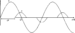 FIGURE 25.5b 1 ... 57 58 59 60 61 62 63 ... 91 |
|
© 2026 AutoElektrix.ru
Частичное копирование материалов разрешено при условии активной ссылки |