 |
 |
 |
| Главная Журналы Популярное Audi - почему их так назвали? Как появилась марка Bmw? Откуда появился Lexus? Достижения и устремления Mercedes-Benz Первые модели Chevrolet Электромобиль Nissan Leaf |
Главная » Журналы » Metal oxide semiconductor 1 ... 60 61 62 63 64 65 66 ... 91 harmonic poUution. However, for very high power apphcations and vohages, these SVCs are unsuitable. In this section we introduce a neutral-point clamped inverter having harmonics contents output voltage far less than those of two-level inverters at the same switching frequency. We also present the modeling and analysis of this new type of inverter used for advanced static VAR compensation. This ASVC uses three-level voltage source inverter (VSI) transforming a dc component to ac through a set of capacitors, which are used as a power storage device. Furthermore, a simplified mathematical model of the ASVC is derived, and various simulation results presented using Matlab. FIGURE 25.51 Details of the control block diagram. 25.7.1 Operating Principles The static VAR compensator (ASVC) that uses a three-level converter of the voltage-source type is shown in Fig. 25.46. The main circuit consists of a bridge inverter made up of 12 power GTOs with antiparallel diodes, which is connected to the three-phase supply through a reactor, X, of smaU value. Two capacitors are connected to the dc side of the converter. The operation principles of the system can be explained by considering the per-phase fundamental equivalent circuit of the ASVC system as shown in Fig. 25.47, as weU as Figs. 25.48 and 25.49. In Fig. 25.47, Уд is the ac mains voltage source. Ii and E are the fundamental components of current and output voltage of the inverter supply, respectively. The ASVC is connected to ac main through a reactor and a resistor R, representing the total loss in the inverter. As shown in Fig. 25.50, by controUing the phase angle a of the inverter output voltage, the dc capacitor voltage can be changed. Thus, the amplitude of the fundamental component E can be controlled. Rs Ls labc abc / dq Block Control Sabc Three-Level PWM 25.7.2 Mathematical Model of the ASVC The modeling of the system is carried out under the following assumptions: All switches are ideal. The source voltage are balanced. The total losses in the inverter are represented by lumped resistor R, and the harmonic contents caused by switching action are negligible. Using matrix form, the mathematical model per phase is given by d Jt
(25.63) The model of the inverter output voltage is given by 2 -1 -1 -1 2 -1 -1 -1 2 L-p31
(25.64) With Ff. function of connection, defining the state of the switch Fji = 1 if the switch is closed and 0 otherwise К = number of the arms {k = 1, 2, 3) / = number of the switches of the arm (/ = 1, 2, 3, 4) FIGURE 25.50 Main circuit and control block diagram. The dc side currents are given by d2 = PulJa + 2324 + 3334*c (25.65) 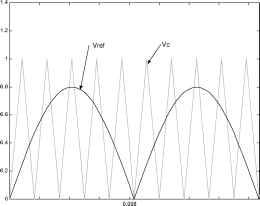 о 0.002 0.004 0.006 0.01 0.012 0.014 0.016 FIGURE 25.52 Three-level PWM switching pattern. The mode of the capacitor voltage is given by
(25.66) 25.7.3 Controller Design In order to synthesize the control strategy of the system, the analysis is carried out on an analysis on {dq) axes [33-35] and the inverter is controlled by a three-level PWM [36]. The ASVC control scheme is illustrated in the block diagram of Fig. 25.50, and Fig. 25.51 illustrates the detailed control loop of the block diagram. To achieve fast dynamic response, it is required that by controlling the phase angle changes the capacitors U and и^2 Small signal equivalent model system is used to calculate the transfer function of the system equation (25.67). QC(5) N(5) a(5) M(5) (25.67) with N{s) = 2 Г 2 +5 + M{s) = 53 + -52 + + Ш2 }5 + 2L2C This circuit consists of a conventional PI controller and a stored switching pattern device used to study the dynamic behavior of the system. The source voltage and the ASVCs current are transformed in the d - q frame for calculating the reactive power generated by the system, which is compared to the reactive power reference. The PLL detects the phase angle of the supply FIGURE 25.53 Simulated voltage and current waveform Vs[vX10], Isa. 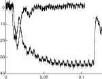 FIGURE 25.54 Phase current in the dq axes, active component isd [A] and reactive component isq [A]. 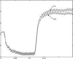 0.2 0.25 FIGURE 25.55 Inverter dc bus vohages U and U2 QcmM[VAR) 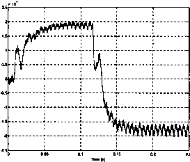 FIGURE 25.56 Reactive power response for 20 kVar step change. 25.7.4 Simulation Results To check the vahdity of the model described above, a set of simulations tests have been carried out to analyse the system under steady-state and transient conditions using Matlab. This wiU certainly lead to the design of a robust controUer [32]. Computer simulation is carried out using the system parameters given by / = 60 Hz, W = 2nf, V, = 550 V, R = 0.4 Q, L = 10 mH, С = 1000 F, MI (modulation index) = 33 Based on the hnear model described above and using the root-locus technique, the parameters of the controller are found to be [27] Kp = 8.24 X 10 К = 1.42 X 10 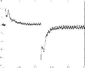 FIGURE 25.57 Variation of the control angle a (°). voltage, which is added to the control variable a (output of the PI controller). This sum controls the frequency of the memorized switching states which are stored in the EPROM. Figure 25.52 shows the PWM three-level pattern obtained from the triangular-sinusoidal control strategy by using the foUowing signals: The reference signals V The triangular carrier The signal control rules are as foUows: If (Vref(k) > 0) and (Vref(k) > Vc) Then Fkl = 1, Fk2 = 1, Fk3 = 0, Fk4 = 0. Else if (Vref(k) < 0) And (abs (Vref(k)) > Vc) Then Fkl = 0, Fk2 = 0, Fk3 = 1, Fk4 = 1. Else Fkl = 0, Fk2 = 1, Fk3 = 1, Fk4 = 0 The amplitude of the reference was adjusted to cause the system to swing to lagging mode. Figure 25.53 shows the simulated current and voltage waveforms to step reference changes from standby to 20Kvar leading and -20Kvar. Figure 25.54 represents transient phase current in the dq axes, isd and isq are the active and reactive components, respectively. Figure 25.55 represents the dc capacitor voltages. We notice a fluctuation of voltages Ui and U2 around an average value and a difference of amplitude and waveforms of the voltages Ui and U2 for the two operating modes. Figure 25.56 shows the simulated transient response of the reactive power response to a sudden change in reference. Figure 25.57 shows the response of control angle a. 25.7.5 Conclusion A study and mathematical modeling of the dynamic performance analysis of an advanced static VAR compensator (ASVC) using a three-level voltage source inverter has been presented in this section. The dynamic behavior of the system was analyzed using Matlab through a set of simulation tests, which have led to the design of an inexpensive controUer for reactive power apphcations. References 1. T. J. E. Miller, Reactive power control in electric systems, (New York, John Wiley and Sons, Inc., 1982). 2. A. Ledu, Pour un reseau electrique plus performant: Le projet FACT, iGE no. 6 Juin, 1992, 105-121. 3. L. Gyugi Compensateur statique denergie reactive de type avance utilisant des thyristors a ouverture par la gachette pour des applications a la distribution publique denergie, Cigre, 22-203, 1990. 4. H. Akagi, Y. Kanazawa, A. Nabae, Generalized theory of the instantaneous reactive power in three-phase circuits, IPEQ Tokyo 83, 1375-1386. 5. Н. Akagi, Y. Kanazawa, A. Nabae, Instantaneous reactive power compensators comprising switching devices without energy storage components, IEEE Trans. Ind. Appl., IA-20, no. 3, May/June 1984. 6. G. Joos, L. Moran, and P. D. Ziogas, Performance analysis of a PWM inverter VAR compensator, IEEE Trans. Power Electronics, 6, no. 3, July 1991, 380-391. 7. L. Moran, P. D. Ziogas, and G. Joos, A sohde-state high-performance reactive-power compensator, IEEE Trans. Ind. Appl., 25, no. 5, Sept./Oct. 1993. 8. L. Moran, P. D. Ziogas, and G. Joos, Analysis and design of a synchronous sohd-state var compensator, IEEE Trans. Ind. Appl, IA-25, no. 4, July/Aug. 1989, 598-608. 9. F. Z. Peng, J-S. Sheng Lai, Generalized the instantaneous reactive power theory for three-phase power systems, IEEE Trans. Instrumentation Measurement, 45, no. 1, Feb. 1996, 1375-1386. 10. A. Tahri, A. Draou, M. Benghanem, A fast current strategy of a PWM inverter used for static var compensation, IEEE lECON Conf. Rec, 1998, 450-455. 11. C. Shauder and H. Mehta, Vector analysis and control of advanced static VAR compensators, lEE Proceedings, 140 no. 4, July 1993. 12. D. R. Trainer, S. B. Tennakoon, R. E. Morrison, Analysis of GTO-based static VAR compensators, lEE Proc. Electr. Power Appl, 141, no. 6, Nov. 1994. 13. C. Boisdon, G. Drown, Les systemes de compensation statique rapide dans les reseaux industriels, RGE, no. 12, Dec. 1983. 14. L. Gyugi, Dynamic compensation of power transmission lines by solid-state synchronous voltage sources, IEEE Trans. Power Delivery, 8, no. 3, July 1993. 15. C. Shauder, et al, Operation of 100 MVAR TVA STATCON, IEEE Trans. Power Delivery, 12, no. 4, 1805-1811, Oct. 1997. 16. L. H. Walker, 10 MW GTO converter for battery peaking service, IEEE Trans. Ind. Appl, 26, no. 1, Jan./Feb. 1990. 17. A. Tahri, Analyse et developpement dun compensateur statique avance pour Г amelioration de la stabilite transitoire des systemes electro-energetiques, Master thesis, 1999, University of Sciences and Technology of Oran U.S.T.O., Algeria. 18. A. Tahri, M. Benghanem, A. Draou, and L. Kotni, A nonlinear control and modelling of an advanced static var compensator, Proceedings of the 1st International Conference on Electrotechnics, ICEL98, 1, 209-214, Oran-Algeria, Oct. 5-7, 1998. 19. R. Benejean, Modeles mathematiques dun groupe turbo-alternateur connecte un reseau de transport electrique, EDF. Bulletin de la direction des etudes et recherches. Serie C. Mathematiques; informa-tique. no. 3/4, 1985. 20. P. M. Anderson et A. A. Fouad, Power system control and stability (The Iowa State University Press, Iowa, 1977). 21. P. Barret, Regimes transitoires des machines tournantes electriques, Les cours de Iecole superieure delectricite, 1982. 22. A. Nabae, I. Takahashi, H. Akagi, A new neutral point clamped PWM inverter, IEEE Trans. Ind. Appl, IA-17, no. 5, Sep./Oct. 1981, 509-517. 23. P. M. Bhagwat, V. Rstetefanovic, Generalized structure of multilevel PWM inverter, IEEE Trans. Ind. Appl, IA-19, no. 6, Nov./Dec. 1983. 24. N. S. Choi, J. G. Cho, G. H. Cho, A general circuit topology of multilevel inverter, Proc. IAS 91, 1991, 96-103. 25. Jih-Sheng Lai and Fang Zheng Peng, Multilevel converters - A new breed of power converters, IEEE Trans. Ind. Appl, 32, no. 3, May/June 1996, 509-517. 26. J. Zhang, A high performance control of three-level IGBT inverters fed AC drives, Proc. PESC 95, 1995, 22-28. 27. J. B. Ekanayake, N. Jenkins, A three-level advanced static var compensator, IEEE Trans. Power Delivery, 11, no. 1, Jan. 1996. 28. M. Carpita, S. Teconi, A novel multilevel structure for voltage source inverter, EPE91, 90-94. 29. A. Draou, M. Benghanem, A.Tahri, Performance analysis of advanced static VAR compensator using three level inverter, Conf. Rec. IEEE/IECON99 USA; Nov. 1999. 30. Prasad N. Enjiti, Ranjit Jakkli, Optimal power control strategies for neutral point clamped (NPC) inverter topology, IEEE Trans. Ind. Appl, 28, no. 3, 558-566, May/June 1992. 31. H. L. Liu, G. Cho, and S. S. Park. Optimal PWM design for high power three-level inverter through comparative studies, IEEE Trans. Power Electronics, 10, no. 1, Jan. 1995. 32. A. Draou, M. Benghanem, and A. Tahri, Modelling and control of a static var compensator using an n.p.c inverter topology, IEEE/ lECONOO, Nagoya, Japan, October 2000. 33. G. C. Cho, N. S. Choi, C. T Rim and G. H. Cho, Modelling, analysing and control of static var compensator using three-level inverter, IEEE Ind. Soc. Annu. Meet, 1992, 837-843. 34. Ekanayake, N. Jenkins., N. B. Cooper, Experimental investigation of an advanced static var compensator, lEE Proc. Gener. Trans. Distrib., 142, no. 2, March 1995. 35. E. M. Berkouk, Y. B. Romdhane, G. Manesse Knowledge and control models for three-level voltage invereters, IMACS95, Allemagne 1995. 36. C. Cho, G. H. Jung, N. S. Choi, G. H. Cho, Analysis and controller design of static var compensator using three-level GTO inverter, IEEE Trans. Power Electron., 11, no. 1, Jan. 1996. 37. M. Benghanem Etude et analyse dun onduleur a trois niveaux utilise comme compensateur statique denergie reactive, Master thesis. University of Sciences and Technology of Oran U.S.T.O., Algeria, 2000. Drive Types and Specifications Yahya Shakweh, Ph. D. Technical Director, FKI Industrial Drives & Controls, Meadow Lane, Loughborough, Leicestershire, LEll INB, UK 26.1 Overview........................................................................................... 629 26.1.1 Introduction 26.1.2 Historical Review 26.1.3 Advantages of VSDs 26.1.4 Disadvantages ofVSDs 26.2 Drive Requirements and Specifications................................................... 633 26.2.1 General Market Requirements 26.2.2 Drive Specifications 26.3 Drive Classifications and Characteristics................................................. 636 26.3.1 Classification by Applications 26.3.2 Classification by Type of Power Device 26.3.3 Classification by Type of Converter 26.4 Load Profiles and Characteristics........................................................... 641 26.4.1 Load Profile Types 26.4.2 Motor-Drive Duty 26.5 Variable-Speed Drive Topologies........................................................... 644 26.5.1 Dc Motor Drives 26.5.2 Induction Motor Drive 26.5.3 Synchronous Motor Drives 26.5.4 Special Motors 26.6 PWM VSI Drive................................................................................. 650 26.6.1 Drive Comparison 26.6.2 Medium-Voltage PWM VSl 26.6.3 Control Strategies 26.6.4 Communication in VSDs 26.6.5 PWM Techniques 26.6.6 Impact of PWM Waveform 26.6.7 Techniques Used to Reduce the Effect of PWM Vohage Waveform 26.6.8 Supply Front End for PWM VSl Drives 26.7 Applications....................................................................................... 657 26.7.1 VSD Applications 26.7.2 Applications by Industry 26.7.3 Examples of Modern VSD Systems 26.8 Summary.......................................................................................... 660 References.......................................................................................... 661 26.1 Overview 26.1.1 Introduction In every industry there are industrial processes of some form that require adjustment for normal operation or for optimum performance. Such adjustments are usually accomplished with a variable-speed drive (VSD) system. VSD systems are an important part of automation. They help to optimize the process and to reduce investment costs, energy consumption, and energy cost. There are three basic types of VSD systems: electrical drives, hydraulic drives, and finally mechanical drives. This chapter focuses mainly on electrical drives. A typical electric VSD system consists of three basic components: the electric motor, the power converter, and the control system, as illustrated in Fig. 26.1. The electric motor is connected directly or indirectly (through gears) to the load. The power converter controls the power flow from an ac supply (often via a supply transformer), to the motor by appropriate control of power semiconductor switches (part of the power converter). With recent advances in power semiconductor and converter topologies, electric variable-speed drives are witnessing a revolution in applications including computer peripheral drives, machine tools and robotic drives, test benches, fans, pumps, and compressors, paper-miU drives, automation, traction, and ship propulsion, and cement-miU and rolling-mill drives. For a proper control, the VSD system variables, both mechanical and electrical, are required for control and protections. Signals are usually derived by sensors, whose outputs are very much dependent on the control strategy employed and the functionality required. This chapter introduces electric variable-speed drives and briefly describes their benefits. It examines their classifications from different perspectives. Their specification requirements to meet applications of different industries are briefly outlined. AC Supply Power converter Control system Load Command signals FIGURE 26.1 VSD schematic diagram. remote control, diagnostics, and trip history. In the low-voltage, low-power arena, packaged electric drives are becoming a commodity product. The disadvantages of such a system are also recognized. They include the need for extra space to accommodate the equipment, cooling, capital cost, noise, and power-system harmonic effects. The following is a brief review of some of the benefits and drawbacks of VSDs. Various VSD topologies have been carefully examined and compared with each other. A selection of modern VSD apphcations are examined and briefly commented upon. 26.1.2 Historical Review To provide an appreciation of electric VSDs, significant dates in the evolution of electric drives are summarized in Table 26.1 [1]. The increased popularity of electric VSD systems witnessed in recent years may be explained by the many advantages a VSD can offer. Such advantages include operation at speeds significantly different from the synchronous speed, energy savings, reduced mechanical shock, improved process performance, improved efficiency, reduced mechanical wear, increased plant life, reduced total ownership costs, reduced system fault levels, and reduced ac disturbances in certain apphcations. Furthermore, modern electric drives are equipped with many features, including serial communication. 26.1.3 Advantages of VSDs VSDs arguably benefit most industrial processes. The challenge has often been how to quantify these benefits. The energy-saving potential of VSD can be easily quantified, particularly for fan and pump drive applications. 26.1.3.1 Energy Saving Electric VSDs provide savings in two ways: (a) directly, by consuming less energy and (b) indirectly, by improving product quality. The latter is often more difficult to quantify. Direct energy savings are only possible with centrifugal loads such as centrifugal pumps and fans. Such loads are often run at fixed speeds. Traditionally, an automatic valve or some other mechanical means is used to vary fluid-flow rates in pumps. However, if a VSD is used, then the motor speeds can be controlled electronically to obtain a desired flow rate and can result in significant energy savings. TABLE 26.1 Historical review of electric drives evolution [1] Year Key Advancement 1886 The birth of electric variable-speed drive system represented by Ward Leonard system 1889 The invention of squirrel-cage induction motor 1890 The slip ring induction motor drive - speed control via rotor resistance control 1904 Kramer drives - introduce a dc link between the slip rings and the ac supply 1911 Variable-speed system based on induction motor with a commutator on the rotor 1923 Ignitron made controlled rectification possible 1928 The invention of thyratron and grid controlled mercury arc rectifiers 1930 dc-to-ac power inversion 1931 ac-to-ac power conversion by cyclo converters 1950 Sihcon-based power switches 1960 Thyristors (SCRs) became available and variable-speed drives began 1961 Back-to-back reversing dc drive introduced 1960s Power semiconductor voltage and current ratings grew and performance characteristics improved 1970 The concept of packaging industrial drives introduced 1972 First integrated motors with dc converter 1973 Isolated thyristor packages 1970s The principle of vector control (field oriented control) evolved 1983 Plastic molding made its first significant impact on VSDs 1985 Direct torque control as a concept 1990 Integrated power modules 1992 A new packaging trend emerged 1996 Universal drives (a general-purpose open-loop vector drive, a closed-loop flux vector drive, and a servo drive) 1998 Complete ac/ac integral converter up to 15kW 1998 Medium-voltage pulse-width-modulated voltage-source inverter drives - became a commercial product On the basis of the laws of affinity for centrifugal loads: Volume of flow is directly proportional to speed Pressure is proportional to the square of the speed Input power is proportional to the cube of the speed The affinity law states that the power consumption is proportional to the cube of the motor speed. This imphes that if the speed is halved, the power consumption is reduced to one-eighth. So, energy savings occur as the requirement for volume decreases. If, for example, a cooling system calls for operation at 50% airflow volume, it requires only 12.5% of the power needed to run the system at 100% volume. Because power requirements decrease faster than the reduction in volume, there is potential for significant energy reduction at lower volume. Generally, centrifugal pumps and fans are sized to handle peak volume requirements that typically occur for short periods. As a result, centrifugal pumps and fans mostly operate at reduced volumes. Opening or closing of a damper aUows the airflow of fans to be controUed. Restricting the airflow causes the motor to work hard even with a low throughput. With a variable-speed drive, the speed of the fan can be reduced, thus giving the opportunity to reduce energy consumption. Adjusting the speed of the motor regulates the airflow. The control can be achieved by monitoring humidity, temperature flow, etc. The lower the required throughput, the more energy is saved. It has been estimated that the payback period of 50-kW fan or pump VSD equipment, operating 2000 hours/year is 1.9 years for operation at 75% speed, and 1.23 years for 50% speed. It has been assumed that the cost of the VSD is £5.5 к and the cost of power is £0.05/kW. 26.1.3.3 Reduced Mechanical Stress (Soft Starts) Starting up a motor direct on line increases stress on the mechanical system, e.g., belts and chains. Direct on-line startup of induction motor is always associated with high inrush current with poor power factor. VSDs can improve the operating conditions for a system by giving a smooth, controlled start and by saving some energy during starting and running. Smoother startup operation wiU prolong life and reduce maintenance, but it is difficult to do more than make an estimate of the cost advantages of these. The benefits of soft start, inherent in VSD, is that it eliminates the uncontroUed inrush of current that occurs when a stationary motor is connected to fuU line voltage, and also the inevitable suddenly applied high startup torque. Benefits are that the power wasted by current inrush is eliminated and that the life of the motor and the driven machine are prolonged by the gentle, progressive application of torque. 26.1.3.4 Improved Electrical System Power Factors When a diode supply bridge is used for rectification, electric variable-speed drives operate at near unity power factor over the whole speed range (the supply delivers mostly real power). When a fully controUed thyristors supply bridge is used (as in dc, cyclo, and current-source drives), the power factor starts at around 0.9 at fuU speed, and proportionally worsens as speed declines due to front-end thyristors (typically 0.45 at 50% speed and 0.2 at 25% speed). Modern pulse-width modulated (PWM) drives convert the three-phase ac line voltage to a fixed-level dc voltage. They do this regardless of inverter output speed and power. PWM inverters, therefore, provide a constant power factor regardless of the power factor of the load machine and the controUer instaUation configuration, for example, by adding a reactor or output filter between the VSD and the motor. 26.1.3.2 Improved Process Control Using VSDs to improve process control results in more efficiently operating systems. The throughput rates of most industrial processes are functions of many variables. For example, throughput in continuous metal annealing depends on the material characteristics, the cross-sectional area of the material being processed, and the temperature of one or more heat zones. If constant-speed motors are used to run conveyors on the line, it must either run without material during the time required to change temperature in a heat zone or produce scrap during this period. Both choices waste energy or material. With VSDs, however, the time needed to change speed is significantly less than the time it takes to change heat-zone temperature. By adjusting the material flow continuously to match the heat zone conditions, a production line can operate continuously. The results are less energy use and less scrap metal. 26.1.4 Disadvantages of VSDs The imphcations of using a VSD is generally space, cooling and capital cost. Some of the drawbacks are: Acoustic noise Motor derating Supply harmonics PWM voltage-source inverter (VSI) drives, equipped with fast switching devices, added other possible problems such (a) premature motor insulation failures, (b) bearing/earth current, and (c) electro-magnetic compatibility (EMC). 26.1.4.1 Acoustic Noise In some instaUations, placing a VSD on a motor increases the motors acoustic noise level. The noise occurs when the drives nonsinusoidal (current and voltage) waveforms produce vibration in the motors laminations. The nonsinusoidal current and voltage waveforms produced by the VSD are the result of the transistor switching frequency and modulation in the dc-to-ac inverter. The switching frequency, fixed or variable, determines the audible motor noise. In general, the higher the carrier frequency, the closer the output waveform is to a pure sine wave. One method of reducing audible motor noise is full-spectrum switching (random switching frequency). VSD manufacturers accomplish full-spectrum switching by an algorithm within the VSD controller. The motor performance is optimized by evaluating motor characteristics, including motor current, voltage, and the desired output frequency. The resulting frequency band, though audible to humans, produces a family of tones across a wide frequency band. So, the perceived motor noise is considerably less than it would be with a single switching frequency. Motor noise may not present a problem. Relevant factors include motor locations and the amount of noise produced by other equipment. Traditionally motor noise level is reduced by adding an LC filter between the VSD and the motor, i.e., reducing the high-frequency component of the motor voltage waveform. Modern PWM inverter drives run at very high switching frequency and with random switching frequency, thus reducing the noise level as well. Various methods have been proposed to reduce the magnetically generated noise that is radiated from inverter-fed induction motors. between the positive and negative sides of the dc link voltage supply. With larger motors that operate from ac supplies up to 6600 V, the rapid rate of change of the voltage apphed to the winding may cause deterioration and failure in the insulation on the entry turns of standard motors. On self-ventilated (fan-cooled) motors, reducing the motor shaft speed decreases the available cooling airflow. Operating a motor at full torque and reduced speed results in inadequate airflow. This consequently results in increased motor insulation temperature. This potentially can be damaging and can reduce the hfe of the motors insulation or cause the motor to fail. One potential solution is to add a constant-speed, separately driven cooling fan to the motor. This approach ensures adequate stator cooling over the whole speed range. However, the rotor will run hotter than designed, as internal airflow remains a function of speed. As there are no windings in the rotor insulation, failure is not an issue, but bearings may run hotter and require more frequent lubrication. Fan-cooled motors with centrifugal loads present less of a problem. Pumps and fans, for example, do not require full torque at reduced speeds. So, in these cases, there is less thermal stress on motors at reduced speeds. Centrifugal load does not cause the motor to exceed thermal limits defined by the insulation system. 26.1.4.2 Motor Heating Most motor manufacturers design their products according to NEMA standards to operate on utility-supplied power. Designers base their motors heating characteristics and cooling methods on power supplied at fixed voltage and frequency. For many drive applications, particularly those requiring relatively low power, inverters with a high switching speed can produce variable voltage and variable frequency with little significant harmonic content. With these, either standard or high-efficiency induction motors can be used with little or no motor derating. However, the inverters used in larger drives have limits on switching rate that cause their output voltages to contain substantial harmonics of orders 5, 7, 11, 13, and so on. These, in turn, cause harmonic currents and additional heating (copper and iron losses) in the stator and rotor windings. These harmonic currents are limited mainly by the leakage inductance. For simple six-step inverters, the additional power losses, particularly those in the rotor, may require derating of the motor by 10-15%. Existing constant-speed drives often have an oversized induction motor. These can usually be converted to variable-speed operation using the original induction motor. Most of the subsequent operation will be at lower load and lower loss than that for which the motor was designed. Modern PWM VSI drives produce a voltage wave with neghgible lower-order harmonics. The wave consists of pulses formed by switching at relatively high frequency 26.1.4.3 Supply Harmonics Current and voltage harmonics in the ac supply are created by VSD (as a nonlinear load) connected on the power distribution system. Such harmonics pollute the electric plant, which could cause problems if harmonic level increases beyond a certain level. The effect of harmonics can be overheating of transformers, cables, motors, generators, and capacitors connected to the same power supply with the devices generating the harmonics. The IEEE 519 recommended practices and requirements for harmonic control in electrical power systems. The philosophy of such regulations is to limit the harmonics injection from customers so that they will not cause unacceptable voltage distortion levels for normal system characteristics and to limit the overall total harmonic distortion of the system voltage supplied by the utility. In order to reduce supply harmonics that are generated by VSDs equipped with a 6-pulse diode bridge rectifier, VSD equipment manufacturers adopt various techniques. Table 26.2 summarizes the most common methods and their advantages and disadvantages [2]. Reference [2] quantifies the cost of these options as a percentage of the cost of a basic system with a 6-pulse diode bridge. For low-power VSDs, the cost of a drive with a line reactor is estimated to be 120% of that without. A VSD with a 12-pulse diode bridge with a polygon transformer is 200%, whereas for a double-wound transformer it is 210%. The most 1 ... 60 61 62 63 64 65 66 ... 91 |
|
© 2026 AutoElektrix.ru
Частичное копирование материалов разрешено при условии активной ссылки |