 |
 |
 |
| Главная Журналы Популярное Audi - почему их так назвали? Как появилась марка Bmw? Откуда появился Lexus? Достижения и устремления Mercedes-Benz Первые модели Chevrolet Электромобиль Nissan Leaf |
Главная » Журналы » Metal oxide semiconductor 1 ... 61 62 63 64 65 66 67 ... 91 Topology Advantages 6-pulse bridge with a choke 12-pulse bridge 6-pulse, fully controlled active front end Harmonic filters Active filter Least expensive - low cost Known technology Simple to apply Eliminates the 5, 7, 17, 19 harmonics Known technology Simple to apply Comprehensive filtering for the drive Cancels all low-order harmonics Filters the installation Reduces the harmonics at the point of common coupling Least expensive filter to install Intelligent fiher Extremely efficient Can be used globally or locally More than one device can be installed on the same supply Disadvantages Bulky Too large a value can reduce available torque Only appHes to the drive Least effective method of filtering Bulky and expensive Only appHes to the drive Many 12-pulse drives on one site will shift the problem to the Uth and 13th harmonics Very expensive Not widely available New technology Needs a site survey Only sized to the existing load Very expensive expensive solution is that with active front end, estimated at 250%. For a 6-pulse converter, п6р± 1 (5, 7, 11, 13, 17, 19, etc.)-order harmonics are generated. To minimize the effects on the supply network, recommendations are laid down IEEE 519 as to the acceptable harmonic limits. For higher drive powers, therefore, either harmonic filtering or use of a higher converter table 26.3 Supply harmonics for different supply-bridge configurations
pulse number is necessary. It is generally true that the use of a higher pulse number is the cheaper alternative. Reference [2] also quantifies the harmonic levels generated by each of the preceding methods: refer to Table 26.3 for a direct comparison. 26.2 Drive Requirements and Specifications 26.2.1 General Market Requirements Some of the most common requirements of VSDs are high rehability, low initial and running costs, high efficiency across speed range, compactness, satisfactory steady-state and dynamic performance, compliance with applicable national and international standards (e.g., EMC, shock, and vibration), durability, high availability, and ease of maintenance and repairs. The order and priority of such requirements may vary from one application to another and from one industry to another. For example, for low-performance drives such as fans and pumps, the initial cost and efficiencies are paramount, as the table 26.2 Techniques used to reduce supply harmonics main reason for employing variable-speed drives is energy savings. However, in other industries such as marine applications, the compactness of the equipment (high volumetric power densities) is a priority requirement because of the shortage of space. In such environments direct raw water cooling is the preferred choice as water is plentiful, and forced water cooling results in a more compact drive solution. In critical VSD applications, such as military marine propulsion, reliability, availability, and physical size are very critical requirements. Cost is relatively less critical. However, achieving these requirements adds to the cost of the basic drive unit. Series and parallel redundancy of components enable the VSD equipment to continue operation even with failed components. These are usually repaired during regular maintenance. In other critical applications (such as hot mill strips or subsea drives) the cost of drive failures could be many times more expensive than the drive itself. For example, accessing a drive down on the seabed, many kilometers below the face, could be very difficult. This section identifies VSD requirements in various drive apphcations in different industries. 26.2.1.1 The Mining Industry The majority of early generation large mine-winders are dc drives. Modern plants and retrofits generally employ cyclo converters with ac motors. However, small mine-winders (below 1 MW) tend to remain dc. The main requirements are as follows: High reliability and availability Fully regenerative drive Small number requiring single-quadrant operation High range of speeds High starting torque required High torque required continuously during slow speed running Low required torque ripple Low supply harmonics Low audible noise emissions Flameproof packaging 26.2.1.2 The Marine Industry The requirements of this industry are the following: Low initial purchase price Reliability Ease of maintenance, i.e., minimum component count, simple design Small size and light weight of equipment Transformerless, water-cooled VSD equipment always preferred Other desirable features include the following: A requirement for the integration of power management functions High volumetric power density (the smallest possible) Remote diagnostics, to allow fault finding by experts onshore in critical situations. Drive powers are commonly in the range of 1 to 6 MW for thrusters, and 6 to 24 MW for propulsion. The evolution in the commercial market is toward powers from 1 to 10 MW for propulsion. Higher powers are required for naval applications. The package drive efficiency must be equal to, or better than, 96%. Noise and harmonics problems are to be considered when using PWM inverters. The supply-side harmonics produced must be capable of being filtered. Above 1 MW, power converters are usually equipped with 12-pulse supply bridge, given todays technology. Two-quadrant operation required in general; hence, diode supply bridge is adequate. The occasional requirement for crash stops forces the use of a dynamic brake chopper. A dc bus can be advantageous for supply to wharf loading equipment, but the drive power ranges are such that commercially available products already adequately serve this application. The use of standard ac machines is desirable; however, if motors matched to the inverter prove to be cheaper, their use could be preferred. Low noise emission (acoustic and electromagnetic) is very important. There is no requirement for high torque at low speed. Programming and expanded input and output capabilities help avoid the need for additional programmable logic control (PLC). 26.2.1.3 The Process Industries The main requirements of this market are as follows: Low initial purchase price (long-term cost of ownership does not generally influence purchasing decision) Efficiency in continuous processes Reliability Ease of maintenance Bypass facility The industry preference is for air-cooled drives. It is perceived that air-cooled drives are less costly than their water-cooled equivalents. Customers often have the belief that water and electricity do not mix well and are wary of problems with leaks. The exception is the offshore industry, where equipment size is paramount, and therefore, water coohng is standard. In general there is no perceived requirement for space saving in the majority of process plants. The desirable features often requested by customers are ease of maintenance and good diagnostic facilities. The market requirement is for cost-effective, stand-alone drives at various power levels from a fraction of a kilowatt up to 30 MW. The use of standard ac machines is desirable. However, if nonstandard, but simpler and cheaper machines can be offered, an advantage could be gained. Two-quadrant operation for fans, pumps, and compressors Four-quadrant operation for some test benches Control that aUows additional functions such as temperature protection, motor bearing temperature, and flow and pressure control No requirement, in general, for field weakening Fiarmonics produced by the drive imposed on the power system that should not require a harmonic filter (harmonics must be minimized) In the low-voltage (LV) arena, the PWM VSI is dominating the market. In the medium-voltage (MV) arena, there are a number of viable drive solutions such as load-commutated inverters (LCIs) and cyclo converters. Fiowever, there is a developing market for MV PWM VSI drives. 26.2.1.4 The Metal Industries The requirements of this industry are as foUows: RehabUity-high avaUabUity Efficiency of the equipment - long term costs of ownership Low maintenance costs (this has been a key factor in the move from dc to ac) Power supply system distortion - more onerous regulations from the supply authorities Initial purchase cost - very competitive market, and large drive costs have a big impact on total project costs Confidence in the supplier and their solution The foUowing is a list of desirable features: Programmable system drives with powerful programming tools Preference for air-cooled stacks (water-cooled is acceptable if a water-to-air heat exchanger is used) Powerful maintenance and diagnostic tools Low EMC noise signature Ability to interface to existing automation system via network, Fieldbus, or serial link Physical size of equipment - often not an important consideration Fire protection systems integral to drive equipment The main market concerns are (a) EMC regulations, (b) effects on motor insulation of higher voltage levels, and (c) cooling with dirty miU water is not acceptable. The maintenance of de-ionised water circuits is a big issue. 26.2.2 Drive Specifications FaUure to properly specify an electric VSD can result in a conflict between the equipments supplier and the end user. Often the cost can be delayed project completion and/or loss of revenue. TABLE 26.4 Typical example of VSD specifications
In order to avoid such a problem, requirement specifications should reflect the operating and environmental conditions (Table 26.4). The equipment suppher and the customer need to work as partners and cooperate from the beginning of the project untU successful commissioning and handover. It is advisable that the enduser procure the complete drive system, including system engineering, commissioning, and engineering support, from one competent suppher. It is one of the first priorities to identify applicable national and international standards on issues related to EMC, harmonics, safety, noise, smoke emissions during faults, dust, and vibration. Overspecifying the requirements could often result in a more expensive solution than necessary. Underspecifying the requirements, result in poor performance and disappointment. As far as end users are concerned, they need to specify the drive interfaces, and the ac input voltage, shaft mechanical power, and shaft speed - the torque and current are calculated from these. Frequency and power factor depend on the choice of motor. For high-power drive, it is always recommended to carry out a harmonic survey. Such a survey wiU reveal the existing level of harmonics and quantify the impact of the new drive on the harmonic levels. 26.3 Drive Classificarions and Characterisrics Table 26.5 illustrates the most commonly used classifications of electric VSDs. In this section, particular emphasis will be given to classification by applications and by converter types. Other classifications, not listed in Table 26.5, include the following: Working voltage: Low voltage <690V, or medium voltage (MV) 2.4-11 kV Current type: Unipolar or bipolar drive Mechanical coupling: Direct (via a gearbox) or indirect mechanical coupling Packaging: Integral motors as opposed to separate motor inverter Movement: Rotary movement, vertical or linear Drive configuration: Stand-alone, system, dc link bus Speed: High speed and low speed Regeneration mode: Regenerative or nonregenerative Coohng method: Direct and indirect air, direct water (raw water and deionized water) Section 26.2 deals with the subject of drive requirements and specifications from the applications point of view; Section 26.5 deals with drive topologies from the point of view of motor classifications. 26.3.1 Classification by Applications Under this classification there are four main groups: Appliances (white goods) General-purpose drives System drives Servo drives Table 26.6 describes the main features of these groups and hsts typical applications. 26.3.2 Classification by Type of Power Device The sihcon-controlled rectifier (SCR), also known as the thyristor, is the oldest controllable sohd-state power device and still the most widely used power device for MV ac voltages between 2.4 and llkV-high-power drive applications. Such devices are available at high voltages and currents, but the maximum switching frequency is limited and requires complex commutation circuit for VSI drive. SCRs are therefore most popular in apphcations where natural commutation is possible (e.g., cyclo converters and LCI current-source converters). The gate turn-off thyristor (GTO) has made PWM VSI drives viable in LV drive applications. The traction industry was one of the first to benefit from such a device on a large scale. Complex gate drive and hmited switching performance, combined with the need for a snubber circuit, limited this device to high-performance apphcations where the SCR-based drives could not give the required performance. The main power devices available in the market can be divided into two groups, as shown in Table 26.7 [3]. Bipo-lar/Mosfet-type transistors experienced significant popularity in the late 1980s; however, they have been replaced by the IGBT, which combines the characteristics of both devices: the current-handhng capability of the bipolar transistor and the ease of drive of the MOSFET. TABLE 26.5 Classifications of electric VSD
TABLE 26.6 Classification of electric VSD by application Type of Drive Appliances General Purpose System Servo Performance Power rating Motor Converter Typical industry Feature Applications Very low Universal and Induction motor; recently, PM and SRM are being used Simple, low cost Home Mass production Low cost Price sensitive Very low power Home appliances such as washing machines, dishwashers, tumble-dryers, freezers Whole range Dc motor, induction motor, and synchronous motor Ac and dc drives with open-loop controller Process Nonregenerative Cost sensitive Low or no overload Low startup Low-performance stand-alone Fans, pumps, and compressors Mixers Simple elevators High Whole range Dc motors Induction motors Synchronous motors PWM drives with dc bus Cyclo converter Good quality control with closed-loop control Needs encoder or observer Metal Accuracy with encoders <0.1% in steady-state and dynamic Good precision and linearity of I/O and control Flexible with operations capability Setup and configuration Communication and feedback Test benches Winders Sectional process lines Elevators Cranes Hoists Very high Low Dc motors Brushless dc motors Induction motor Stepper motors Actuators Dc drives, ac drives, special motor drives Tendency toward brushless dc motors Automation Closed-loop, PM motor > 1000 Hz torque response Precise and rapid response Frequent full- speed reversal High precision Linearity of 1/Os Positioning, pick and place, robotics, coordinate control, machine tools Traction inverters are designed for dc link voltages between 650 V dc and 3kV dc with ratings up to 3MW. The first generation of widely used traction inverter equipment was GTO based; the latest generation is almost exclusively IGBT based. Conversion to IGBT has enabled a 30% to 50% reduction in cost, weight, and volume of the equipment. Early attempts to use GTOs in MV applications failed because of their high cost, snubber requirements, and associated snubber energy loss, which is proportional to the square of the supply voltage. Energy recovery circuitry enables recov- ery of most of the snubber energy but added to the cost and complexity of the converter. With high-voltage IGBT and IGCT, MV PWM VSI have become commercially available with supply voltage up to 6.6 kV, and power rating in excess of 19 MW. 26.3.3 Classification by Type of Converter The power converter is capable of changing both its output voltage magnitude and frequency. FLowever, in many applica- TABLE 26.7 Power devices used in VSD converters [3] Group 1: Thyristors Group 2: Transistors This group covers devices having a four-layer, three-junction monolithic structure. They are characterized by by low conduction losses and high surge and current carrying capabilities. They operate as an on/off switch. The most popular types of devices listed under this group: Silicon-controlled rectifier (SCR) Gate turn-off thyristor (GTO) MOSFET- controlled thyristor (MCT) Field-controlled thyristor (FCT) Emitter-switched thyristor (EST) MOS turn-off thyristor (MTO) Integrated-gate commutated thyristor (IGCT) Switches listed under this group are basically three-layer two junction structure devices, which operate in switching and linear modes. They are best recognized for ruggedness of their turn-off capabilities. Bipolar junction transistor (BJT) Darhngton transistor MOSFET Injection-enhanced gate transistor (lEGT) Carrier stored trench-gate bipolar transistor (CSTBT) Insulated-gate bipolar transistor (IGBT) First published in Power Engineering Joumal, Dec. 1999, Vol. 13, No. 6, pp. 297-307. Used with permission, ©1999 lEE. tions these two functions are combined into a single converter by the use of the appropriate switching function, e.g., PWM. By appropriate control of the stator frequency of ac machines, the speed of rotation of the magnetic field in the machines air gap and thus output speed of the mechanical drive shaft can be adjusted. As the magnetic flux density in the machine must be kept constant under normal operation, the ratio of motor voltage over stator frequency must be kept constant. The input power of the majority of VSD systems is obtained from sources with constant frequency (e.g., ac supply grid or ac generator). In order to achieve a variable-frequency output energy, an ac/ac converter is needed. Some converters achieve direct power conversion from ac/ac without an intermediate step (e.g., cyclo converters and matrix converters). Other converters require a dc link (as current source or voltage source). In all ac variable-speed drives, the direction of shaft rotation is reversed by simply changing the phase rotation of the inverter through the sequence of driving the switches. 26.3.3.1 Dc Static Converter This drive employs the simplest static converter. It is easily configured to be a regenerative drive with a wide speed range. Table 26.8 summarizes its key features. High torque is available throughout the speed range with excellent dynamic performance. Unfortunately, the motor requires regular maintenance and the top speed often is a limiting factor. Commutator voltage is limited to around 1000 V, and this limits the maximum power available. The continuous stall torque rating is very limited because of the motors commutator. 26.3.3.2 Direct ac/ac converters 2633,2,1 Cyclo Converter A typical cyclo converter comprises the equivalent of three antiparallel 6-pulse bridges (for regenerative converter) whose output may be operated in all four quadrants with natural commutation. The main features of cyclo converters are listed in Table 26.8. This type of drive is best suited to high- performance, high-power >2MW drives where the maximum motor frequency is less than 33% of the mains frequency. 26,3,3,2,2 Matrix Converter The force-commutated cyclo converter (better known as a matrix converter) represents possibly the most advanced state of the art at present, enabling a good input and output current waveform, as well as eliminating the dc link components with very little limitation in input to output frequency ratio. This type of converters is still at its early stages of development. The main advantage of this drive is the ability to convert ac fixed-frequency supply input to ac output without a dc bus. It is ideal for integrated motor drives with relatively low power ratings. Major drawbacks include (a) the increased level of silicon employed (bidirectional switches), (b) the fact that its output voltage is always less than its input voltage, and (c) the complexity of commutation and protection. Matrix converters provide direct ac/ac power conversion without an intermediate dc hnk and the associated reactive components. They have substantial benefits for integrated drives as outhned below: Reduced volume due to the absence of dc link components Ability to operate at the higher thermal limit imposed by the power devices Reduced harmonic input current compared to diode bridge Ability to regenerate into the supply without dumping heat in dynamic braking resistors Matrix converters have not been commercially exploited because of voltage ratio limitation, device count, and difficulties with current commutation control and circuit protection. 26.3.3.3 Current-Source Inverter (CSI) The output of this inverter is rectangular blocks of current from the motor bridge supplied from a supply converter whose output is kept at constant current by a dc link reactor and current servo. This type of inverter is typically based on fast thyristors. 26.3.3.3.1 Load-Commutated Inverter (LCI) Natural commutation of thyristors is usually achieved with synchronous machines at speeds >10%. Natural commutation is induced as a result of the presence of the motors electromotive force (EMF). This is called load commutation; hence the drives other name of LCI. At low speeds the motor voltage is too low to give motor bridge commutations. This is achieved by using the supply converter. Induction-motor LCI drives can be supphed by adding a large capacitor on the motor terminals. The LCI drive covers a wider speed range (up to 10,000 rpm) with power rating up to 100 MW. It gives full-load torque throughout the speed range with moderate dynamic performance. Its simple converter design combined with a maintenance-free motor design (both induction and synchronous) has increased the popularity of these drives. It is still a popular solution for high-power drives (e.g., conveyors, pumps, fans, compressors, and marine propulsion). The LCI drive has limited performance at low speeds. It also suffers from torque pulsation at 6 and 12 times motors frequency and beat frequencies. Critical speeds can excite mechanical resonance. Its ac power factor varies with speed. Torque pulsations can be reduced in 12-pulse systems if required. 26.3.3.3.2 Forced Commutated Inverter (FCI) Externally commutated current source converters with an induction motors are also a viable solution. To compensate for the 26 Drive Types and Specifications TABLE 26.8 Converter topologies Converter Schematic Features (a) Controlled rectifier (b) Cyclo (c) Matrix (d) LCI (e) FCl (f) VSl (g) Kramer   4ф о ZSZS2S о Dc motor Fully controlled SCR converter Controlled dc voltage Simple converter topology Power factor is a function of speed Induction motor and synchronous motor Direct ac/ac power conversion 3 X 6-pulse SCR-based fully controlled converters - APT for fully regen Natural commutation Low supply harmonics, 18-pulse Power factor is a function of speed Squirrel-cage induction motor Synchronous motor Direct ac/ac power conversion Forced commutated, reverse conducting switches 4-quadrant operation inherent PWM in/PWM out Controlled power factor Synchronous motor Simple converter arrangement Power factor is function of speed Load-commutated SCRs Synch motor requires excitation Suffers from torque pulsation at low speeds Squirrel-cage induction motor Similar to LCI Requires output capacitors for commutation Requires a diverter commutation circuit for commutation at low speeds Torque pulsation and resonance Synchronous and squirrel-cage induction motors. 6-pulse diode front end Good power factor across speed range Dc link voltage source PWM output voltage Wound-rotor induction motor with slip rings. Small energy recovery converter Any type converter may be used between slip ring and ac input inductive component in the motor current, a bank of capacitors is usually used at the motor terminals. The capacitor current is proportional to the motor voltage and frequency. Load commutation occurs at high speed where the compensation current is high enough. Forced commutation occurs at lower speed where the capacitive current is too low for compensation. Forced commutation is achieved using various techniques. The one shown in Table 26.8 is based on a dc link diverter that consists of a GTO and loading equipment in parallel with the diverting/compensating capacitor. Modern drives employ forced commutated devices, such as reverse blocking GTOs and IGCTs. 26.3.3.4 Slip Power Recovery (Kramer) In this type of converter, which is described in Table 26.8, the rotor current of a shp ring wound rotor induction motor is rectified and the power then reconverted to ac at fixed frequency and fed back into the supply network. For traditional designs, the low-frequency slip-ring currents are rectified with a diode bridge and the dc power is then inverted into ac power at mains frequency. The traditional designs had poor ac mains dip immunity, high torque pulsation, and high levels of low-frequency ac supply harmonics. The latest generation of this type of drive is called the rotor drive and uses PWM-VSI inverters for the rotor and ac supply bridges. This keeps sine wave currents in the ac rotor circuits. The drive has many advantages over traditional circuits: No torque pulsation Low ac harmonics Very high immunity to ac supply dips table 26.9 Drive features
Due for publication in Power Engineering Joumal in June 2001. Used with permission, lEE. Very cost effective if a limited speed range is required, but still requires a separate starter Inherent ability to run at rated speed without electronic circuits Converter cost reduced by 2:1 if uses the ib speed ability to give a speed range 26.3.3.5 PWM VSI Converter The availability of power electronics switches with turn-off capability, e.g., FETs, BJTs, IGBTs, and GTOs, has currently favored drives with voltage-fed PWM converters on induction. PWM VSI drives offer the highest possible performance of all variable speed drives; refer to Table 26.9. Recent improvements in switching technology and the use of microcontroUers have greatly advanced this type of drive. The inverters are now able to operate with an infinite speed range. The supply power factor is always near unity. Additional hardware is easily added if there is a requirement to regenerate power back into the mains supply. Motor ripple current is related to the switching frequency and in large drives the motor may be derated by less than 3%. 26.3.3.6 Comparison Table 26.9 summarizes the main features of aU types of converter drives discussed above and assess their merits and drawbacks. It also illustrates typical applications. 26.4 Load Profiles and Characteristics The way the drive performs is very much dependent on the load characteristics. Four load characteristics are now described. 26.4.1 Load Profile Types In the literature, four different load profiles have been described [4] (see Table 26.10): I. Torque proportional to the square of the shaft speed (variable torque) II. Torque linearly proportional to speed (inear torque) III. Torque independent of speed (constant torque) IV. Torque inversely proportional to speed (inverse torque) 26.4.2 Motor-Drive Duty 26.4.2.1 Duty Cycle The size of the driven motors is generally chosen for continuous operation at rated output, yet a considerable proportion of motor drives are used for duties other than continuous. As the output attainable under such deviating conditions may differ from the continuous rating, fairly accurate specification TABLE 26.10 Load characteristics Type 1 Type 11 Type 111 Type IV T =/(speed) P = /(speed) Low startup torque Best suited for energy saving Torque-speed curve is required when specifying a drive Axial and centrifugal pumps Axial and centrifugal ventilators Screw and centrifugal compressors Centrifugal mixers Agitators Power 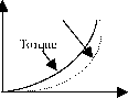 T = /(speed) P =/(speed) Information about process is needed (e.g., density, consistency, viscosity, temperature) Mixers Stirrers 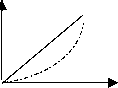 T = Constant P =f (speed) At startup the torque may be higher than nominal, e.g., static friction with conveyor belts Vertical and horizontal forces need to be taken into consideration for inchned conveyors Extrusions, draw-benches Paper and printing continuous machines Volumetric gear pumps/pistons pumps, etc. Piston compressors Conveyor machines Lift machines T =/(1/speed) P = Constant Mostly dominated by dc drives, but modern PWM VSl is talking over Certain loads such as windind and reeling machinery required closed-loop controls Lift machines Reciprocating rolling mills Winding machines Lathes Winders Reelers Wire drawers Web-feed printing machines  of the duty is an important prerequisite for proper planning. There is hardly a limit to the number of possible duty types. In high-performance applications, such as traction and robotics, the load and speed demands vary with time. During acceleration of traction equipment, a higher startup torque (typically twice the nominal torque) is required; this is usually followed by cruising and deceleration intervals. As the torque varies with time, so does the motor current (and motor flux linkage level). The electric, magnetic, and thermal loading of the motor and the electric and thermal loading of the power electronics converter are definite constraints in a drive specification. Table 26.11 categorizes operating duties into eight major types [5]. 26.4.2.2 Mean Output Variation of the required motor output during the periods of loaded operation is among the most frequent deviations from the duty types defined in Table 26.11. In such cases the load TABLE 26.11 Definition of load cyclic duties: VDE0530, in accordance with lEC 34-1 [5] Duty Type Representation Description SI: Continuous running duty S2: Short-time duty S3: Intermittent periodic duty with a high startup torque S4: Intermittent periodic with a high startup torque S5: Intermittent periodic duty with high startup torque and electric braking Operation at constant load of sufficient duration for the thermal equilibrium to be reached. Operation at constant load during a given time, less than required to reach thermal equilibrium, foUowed by a rest and deenergized period of sufficient duration to reestabUsh machine temperatures within 2°C of the coolant. A sequence of identical duty cycles, each including a period of operation at constant load and a rest and deenergized period. In this duty type the cycle is such that the starting current does not significantly affect the temperature rise. A sequence of identical duty cycles, each cycle including a significant period of starting, a period of operation at constant load, and a rest and deenergized period. A sequence of identical cycles, each cycle consisting of a period of starting, a period of operation at constant load, a period of rapid electric braking, and a rest and deenergized period. S6: Continuous-operation periodic duty A sequence of identical duty cycles, each cycle consisting of a period of operation at constant load and a period of operation at no load. There is no rest and deenergized period. S7: Continuous-operation periodic duty with high startup torque and electric braking S8: Continuous-operation periodic duty with related load/speed changes A sequence of identical duty cycles, each cycle consisting of a period of starting, a period of operation at constant load, and a period of electric braking. There is no rest and deenergized period. A sequence of identical duty cycles, each cycle consisting of a period of operation at constant load corresponding to a predetermined speed of rotation, followed by one or more periods of operation at other constant loads corresponding to different speeds of rotation. There is no rest and de-energized period. 1 ... 61 62 63 64 65 66 67 ... 91 |
|
© 2026 AutoElektrix.ru
Частичное копирование материалов разрешено при условии активной ссылки |