 |
 |
 |
| Главная Журналы Популярное Audi - почему их так назвали? Как появилась марка Bmw? Откуда появился Lexus? Достижения и устремления Mercedes-Benz Первые модели Chevrolet Электромобиль Nissan Leaf |
Главная » Журналы » Metal oxide semiconductor 1 ... 62 63 64 65 66 67 68 ... 91 (defined as current or torque) is represented by the mean load. This represents the RMS value, calculated fi-om the load vs time characteristics. The maximum torque must not exceed 80% of the breakdown torque of an induction motor. If the ratio of the peak torque to the minimum power requirements is greater than 2:1, the error associated with using the RMS output becomes excessive and the mean current has to be used instead. No such mean value approximation is possible with duty type S2, which therefore necessitates special enquiry. Careful assessment of duty types S2 to S8 reveals that there exist two distinct groups: Duties S2, S3 and S6 permit up rating of motors relative to the output permissible in continuous running duty (SI). Duties S4, S5, S7 and SB requiring derating relative to the output permissible in continuous running duty (SI). 26.4.2.3 Thermal Cycling The drive duty cycle also affects the reliability and the life expectancy of power devices. Repetitive load cyclic duty results in additional thermal stresses on power devices. Frequent acceleration and deceleration of drives results in repetitive junction temperature rise and falls at the cyclic duty. The life expectancy of devices is often determined by the maximum allowed number of cycles for a given power device junction temperature rise. Although this is true for aU types of power devices, it is more critical for IGBTs where wire bonds and solder layers are used. In modern IGBT-based converter design, the maximum junction temperature rise of the IGBTs is hmited to a level, which ensures a conservative number of thermal cycles over the lifetime of the drive. Typical junction temperature rise is 30 °С for a repetitive cychc duty (e.g., steel miU) and 40 °С for nonrepetitive cyclic duty (e.g., fan pumps). 26.4.2.4 Multiquadrant Operation Fully regenerative electric VSDs offer a rapid regenerative dynamic braking in both forward and reversed directions. Operation in motoring implies that torque and speed are in the same direction (QI, III). In regenerative braking the torque is opposite to the speed direction (QII, IV) and the electric power flow in the motor is reversed. (See Fig. 26.2.) Positive power flow of electric energy means that electric power is drawn from the power supply via the power electronics converter by the motor; negative power flow refers to electric power delivered by the motor in the generator mode to the power electronics converter. This could be regenerated back to the supply, or dissipated as heat in the dynamic brake dissipative mechanism. Torque
Speed -► FIGURE 26.2 Operating regions of electric VSD. For regenerative drive, the power electronics converter has to be designed to be able to handle bidirectional power flow. In low- and medium-power converters (say <500kW) with slow dynamic braking demands, the generated power during the braking periods is interchanged with the strong filter capacitor of power electronics converter, or dc (dynamic) braking is used. 26.4.2.5 Dynamic Braking Energy There exist two types of energy stored in VSD, which need to be dealt with during dynamic braking: Inertia or kinetic energy loads. Typically moving (rotating or linear) machines. These would decelerate naturally to rest. Braking can speed up the process cycle for the sake of productivity. Mass or potential energy loads. Typically hoists or lifts - which would run on or even accelerate. Braking must apply fuU power to maintain constant speed while the load is lowered. The drive losses, mechanical resistance, and transmission efficiency work in favor of deceleration, reducing the braking power demand. The energy regenerated by potential energy loads depends on maximum power and both the overrun time and the decelerating time. The braking time and the duty cycle time are decided by the requirements of the process system, but note particularly the effect of varying the braking duty cycle time and the deceleration time. For dc injection braking, the kinetic energy of the motor-load system is converted to heat in the motor rotor. For fast and frequent generator braking, the power electronics converter has to handle the generated power either by a controlled dynamic brake chopper (with braking resistor) or through bidirectional power flow. The power losses in the converter can assist in dynamic braking. For a fast speed response, modern variable-speed drives may develop a maximum transient torque up to base speed and maximum transient power up to maximum speed, provided that both the motor and the power electronics converter can handle these powers. For a 200-kW dynamometer drive application, a rapid change of torque from full positive torque to full negative torque is required in less than 10 ms. 26.5 Variable-Speed Drive Topologies In this section drive topologies are classified according to the motor they employ. Various pubhcations have dealt with this subject [6, 7]. The most common motors are illustrated in Fig. 26.3. 26.5.1 Dc Motor Drives Until recently, the dc motor drive was the most commonly used type of electric-variable speed drive; with very few exceptions it is the least expensive. The mechanical commutator is an electromechanical dc to ac bidirectional power flow power converter, as the currents in the rotor armature coils are ac while the brush current is dc. The dc drive is well known, well proven, and widely applied, yet its popularity is in relative decline because of the emergence of the more robust, lower-cost squirrel-cage induction motor drive. Electric Variable Speed Drives Special drives Stepper Motor Integral motor Induction Motor Synchronous Motor Squirrel cage Cyclo j Matrix j CSI j VSI j FCI(IM) j LCI(SM) j FIGURE 26.3 Classification of electric VSDs. Unfortunately, the mechanical commutator, though not bad in terms of losses and power density, has serious commutation current and speed limits and thus limits the power per unit to 1-2 MW at 1000 rpm and may not be at all accepted in chemically aggressive or explosion-prone environments. The application of the dc drive has been restricted in hazardous areas because of the very hmited availability of flameproof dc machines. Commutator and brush maintenance is difficult in such environments. Furthermore, continuous sparking at the brushes is virtually inevitable at full load output. Because of the inherent ease of speed control of the separately excited dc machine, dc drives found popularity in early electric drive applications, by varying the applied armature voltage. This variable armature voltage is simply generated by phase-controlled rectification, and this technique has now almost entirely replaced the Ward-Leonard systems previously used. The ac/dc converter offers a variable dc voltage, which is capable of four-quadrant operation (positive and negative dc voltage and dc current output). Permanent magnet-excited brushed motors have been used in numerous applications for sometime, particularly in nonregenerative drive applications. Motor output torque is approximately proportional to armature current and motor speed approximately proportional to converter output voltage. Speed control by sensing armature voltage is therefore feasible, giving an accuracy of around 5%. Provided the motor excitation is kept constant, the dc drive power factor is proportional to motor speed. Since most pumps, compressors, and fans demand a torque proportional to the square of speed, constant excitation systems are used and so the preceding relationship apphes: A typical power factor at maximum rated speed for a dc drive is 0.85. This relationship applies to many other types of electric drives. If a slow dynamic response is satisfactory, regeneration to the mains supply is achieved by reversing either the motor field or the armature connection. Alternatively, regeneration with faster response is achieved by connecting another thyristor bridge in antiparallel with the main bridge (Fig. 26.4a). In this case fast response is possible with changeover times of <15ms between full torque motoring to full torque regenerating. The 6-pulse drive configuration is acceptable for powers Field 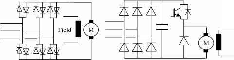 (a) (b) FIGURE 26.4 Dc drive: (a) with fully controlled antiparallel supply bridge; (b) diode rectifier with dc chopper. up to 1 MW. This hmitation does not arise from any semiconductor device hmitation, but is due to ac hne current harmonics the converter generates. A force-commutated or chopper converter for dc motors uses the principle of variable mark-space control using a thyristor or transistor solid-state switch. With a diode front-end converter, a fixed, smoother dc supply is derived from the mains by uncontrolled rectification and is rapidly applied, removed, and reapphed to the machine for adjustable intervals, thus applying a variable mean dc voltage to the dc motor; refer to Fig. 26.4b. This type of dc drive has the advantage of high (near-unity) power factor at all motor speeds and much reduced harmonic spectrum. 26.5.2 Induction Motor Drive 26.5.2.1 Squirrel-Cage Induction Motor Squirrel-cage induction motors are simpler in structure than dc motors and are most commonly used in the VSD industry. They are robust and reliable. They require little maintenance and are available at very competitive prices. They can be designed with totally enclosed motors to operate in dirty and explosive environments. Their initial cost is substantially less than for commutator motors and their efficiency is comparable. All these features make them attractive for use in industrial drives. The stator windings develop a rotating magnetic flux rotating at synchronous speed. This speed depends on the motor pole number and supply frequency: The rotating flux intersects the rotor windings and induces an EMF in the rotor winding, which in turn results in circulating current. The rotor currents produce a second magnetic flux, which interacts with the stator flux to produce torque to accelerate the machine. As the rotor accelerates, the induced rotor voltage falls in magnitude and frequency until an equilibrium speed is reached. At this point the induced rotor current is sufficient to produce the torque demanded by the load. The rotor speed is shghtly lower than the synchronous speed by the slip frequency, typically 3%. In order to ensure constant excitation of the machine, and to maximize torque production up to the base speed, the ratio of stator voltage to frequency needs to be kept approximately constant. An induction motor drive has three distinct operating regions: (a) Constant torque. The inverter voltage is controlled up to a maximum value limited by the supply voltage. As the motor speed and the voltage are increased in proportion, constant V/F, the rated flux linkage is maintained up to the base speed. Values of torque up to the maximum value can be produced at speeds up to about this base value. The maximum available torque is proportional to the square of the flux linkage. Typically, the induction motor is designed to provide a continuous torque rating of about 40-50% of its maximum torque. (b) Constant power. For higher speed, the frequency of the inverter can be increased, but the supply voltage has to be kept constant at the maximum value available in the supply. This causes the stator flux linkage to decrease in inverse proportion to the frequency. Constant power can be achieved up to the speed at which the peak torque available from the motor is just sufficient to reach the constant power curve. A constant-power speed range of 2-2.5 can usually be achieved. Within this range, the motor frequency is increased until the machine hmit is reached. (c) Machine limit (pullout torque). Once the machine limit has been reached, the torque faUs off in proportion to the square of motor frequency. Operation at the higher end of this speed range may not be feasible as the motor power factor worsens. This in turn results in a higher stator current than the rated value. The motor heating may be excessive unless the duty factor is low. Induction motors are used in applications requiring fast and precise control of torque, speed, and shaft position. The control method widely used in this type of application is known as vector control; a transient response at least equivalent to that of a commutator motor can be achieved. The voltage, current, and flux linkage variables in this circuit are space vectors from which the instantaneous values of the phase quantities can be obtained by projecting the space vector on three radial axes displaced 120° from each other. The real and imaginary components of the space vectors are separated, resulting in separate direct and quadrature axis equivalent circuits but with equal parameters in the two axes. Changes in the rotor flux linkage can be made to occur only relatively slowly because of the large value of the magnetizing inductance of the induction motor. Vector control is based on keeping the magnitude of the instantaneous magnetizing current space vector constant so that the rotor flux hnkage remains constant. The motor is supplied from an inverter that provides an instantaneously controlled set of phase currents that combine to form the space vector, which is controlled to have constant magnitude to maintain constant rotor flux linkage. The second component is a space vector, which is in space quadrature with the instantaneous magnetizing current space vector. This component is instantaneously controUed to be proportional to the demand torque. To the extent that the inverter can supply instantaneous stator currents meeting these two requirements, the motor is capable of responding without time delay to a demand for torque. This feature, combined with the relatively low inertia of the induction motor rotor, makes this drive attractive for high-performance control systems. Vector control requires a means of measuring or estimating the instantaneous magnitude and angle of the space vector of the rotor flux hnkage. Direct measurement is generally not feasible. Rapid advances are being made in devising control configurations that use measured electrical terminal values for estimation. 26.5.2.2 Slip-Ring (Wound-Rotor) Induction Motor Drive Wound-rotor induction motors with three rotor slip rings have been used in adjustable-speed drives for many years. In an induction motor, torque is equal to the power crossing the air gap divided by the synchronous mechanical speed. In early slip-ring induction motor drives, power was transferred through the motor to be dissipated in external resistances, connected to the slip-ring terminals of the rotor. This resulted in an inefficient drive over most of the speed range. More modern slip-ring drives use an inverter to recover the power from the rotor circuit, feeding it back to the supply system. The speed of slip-ring induction motor can be controlled by: Stator frequency control Rotor frequency control Rotor resistance control Shp energy recovery (Kramer drive) The last two methods are traditionally used on cost grounds. Addition of rotor resistance for starting large induction motors is well known. Adding rotor resistance alters the speed at which maximum motor torque is developed. Unfortunately, power dissipates as heat in the rotor resistance bank. Earher means to overcome this shortcoming were to convert the rotor power to dc, and feed a dc motor on the same shaft. The rotor slip energy, when running at reduced speed, is therefore reconverted to mechanical power. This is the Kramer system. The disadvantages of this approach were the extra maintenance and capital costs. The Kramer drive overcomes these shortcomings by replacing the dc machine with a line-commutated inverter that returns the slip energy directly to the ac line. A key advantage of the Kramer drive system is that the slip energy recovery equipment need only be rated for a fraction of the maximum motor rating, typically 30%. This is true when a small speed range is required and provided that a separate means is provided of starting the motor. This is because the motor rotor current is proportional to torque and the rotor voltage inversely proportional to speed. If the slip-energy recovery converter can be rated to withstand full rotor voltage (at start up), a controlled speed range of zero to maximum could be achieved. However, this is generally only feasible on motors below 2000 kW where the rotor voltage is sufficiently low for an economic inverter package. Secondly, if a full speed range is needed, the slip-energy recovery converter has to be rated at full motor power, so Kramer drives become uneconomic for wide speed ranges. The overall system power factor would be very low for a wide-speed-range system. For these reasons, Kramer drives are very suitable for high-power drives (>200kW) where a small speed range is required. Pump and fan drives therefore present good economic applications. Kramer drives have also been used for low-speed-range endurance dynos using the recovery system to the control torque of the induction generator. As with all line-commutated converters and inverters, current harmonics are produced, and these can be reduced to acceptable values. However, as the slip-energy recovery network is only power-rated in direct proportion to the speed reduction required (assuming constant load torque), the magnitudes of the harmonic currents generated are proportionally less than with drives where the solid-state converters have to handle the whole drive power. Harmonics of the rotor rectifiers are transmitted through the rotor and appear as noninteger harmonics in the main supply. The main disadvantages of the slip-ring induction motor drive are (a) the increased cost of the motor in comparison with a squirrel cage, (b) the need for slip-ring maintenance, (c) difficulty in operating in hazardous environments, (d) the need for switchable startup resistors, and (e) the poor power factor compared with other types of drive. 26.5.3 Synchronous Motor Drives If the induction motor were to rotate at the synchronous speed by an external means, the frequency and magnitude of the rotor currents would become zero. If an external dc power supply were connected to the rotor winding, then the rotor would become polarized in a similar way to a permanent magnet. The rotor would pull into step with the air-gap-rotating magnetic field, generated by the stator but lagging it by a small constant angle referred to as the load angle. The load angle is proportional to the torque applied to the shaft, and the rotor keeps rotating at synchronous speed, provided that the dc supply is maintained to the rotor field winding. The magnetic flux produced by the rotor winding intersects the stator windings and generates a back EMF, which makes the synchronous motor significantly different from the induction motor. As with the induction motor drive, the requirement is to keep the ratio V/F constant (i.e., to vary both the stator frequency and the applied voltages in proportion to the desired motor speed). The supply bridge converter is phase controlled, generating an adjustable dc current in the dc link choke. To generate maximum torque from the synchronous motor, this current is switched into the motor stator windings at the correct phase position with respect to the rotor angular position as detected by the position sensor by the inverter bridge. When running above about 10% speed, the back EMF generated by the synchronous motor is sufficient to commutate the current into the next arm of the inverter bridge. So, as this type of inverter is machine (motor) commutated, the inverter configuration is merely that of a conventional dc drive. The complexity, expense, and hmited power capability of the force-commutated circuitry is therefore avoided. The motor back EMF is insufficient for thyristor commutation at low speeds. The technique here, therefore, is to rapidly phase back the supply converter bridge to reduce the dc hnk current to zero and after a short delay (to ensure that all thyristors in machine bridge are turned off) reapply dc current when the correct thyristor trigger pattern has been reestabhshed. As the motor speed, and thus back EMF, increase to a value sufficient for machine commutation, changeover to continuous dc link current operation is effected. During the starting mode, the correct inverter bridge firing instant is determined by a rotor position sensor mounted on the motor shaft whose angular position is detected by opto or magnetic probes. In the machine-commutated mode, sensing of stator voltage is used. To develop maximum torque in the low-speed or pulsed mode, angular rotor position sensing is necessary. Fiowever, if less than fuU load torque availability at low speed can be tolerated, the inverter system can be set to produce a low fixed frequency in the pulsed mode. This frequency is then increased, as motor rotation is detected (either in steps or on a preset ramp rate) until sufficient back EMF is generated to facilitate changeover to the voltage-sensing mode. As previously stated, the key advantage of this type of drive is that aU thyristor devices are line or machine commutated. Complex forced commutation circuitry is avoided and fast turn-off thyristors are unnecessary. Inverter systems of this type can therefore be built at very high powers, up to 100 MW. Also, as a result of avoiding force commutation, converter efficiency is high, typically 98%. The thyristors in the machine inverter bridge must be triggered at an angle that gives sufficient time for commutation from one device to the next. This results in the synchronous motor operating at a high leading power factor. Fiowever, the power factor is proportional to speed. This type of drive is inherently reversible and regenerative. For regenerative operation, the inverter bridge is triggered in the fully advanced position. A dc output voltage is generated at the dc side of the supply converter bridge. This converter bridge is now triggered in the regenerative mode, thus back-feeding power to the supply system. Speed reversal is achieved by altering the sequence in which the thyristors in inverter bridge are triggered. This type of drive is widely apphed over a wide power range, as it comprises an efficient motor and simple and efficient converter. At lower powers, permanent magnet motors are more popular. Unlike the induction motor, the synchronous type requires two types of converter. The first is for main power conversion; the second is low power for field excitation. The field converter feeds the rotor exciter winding through slip rings and brushes, or alternatively a brushless exciter can be used. Coordinated control of the two converters provides for active power and reactive power control and for efficient wide-speed-range control in high-power applications. For high-power applications, synchronous motors are preferred because of their ability to control reactive power flow through appropriate control of excitation. Synchronous motors tend to have wider speed range and higher efficiency. Fiowever, synchronous motors are generally more expensive than induction motors. With modern high-power PWM VSI drives, a synchronous motor can be driven for same inverter with vector control methods. 26.5.4 Special Motors Motors under this category employ power electronics converters for normal operation. Generally, this type of motor has a large number of phases in order to limit torque pulsation and self-start from any rotor initial position. This is a new breed of motors, which can be fed through a unipolar or bipolar current. Also, they have singly salient or doubly salient magnetic structures with or without permanent magnets on the rotor. 26.5.4.1 Brushless dc Motor (BDCM) Drive This type of machine has a similar construction to a standard synchronous machine, but the rotor magnetic field is produced by permanent-magnet material. A position sensor is used to ensure synchronism between the rotor position and the stator MMF via drive signals to the inverter. The use of new magnet materials characterized by high coercive-force levels has reduced magnet sizes and largely overcome the demagnetization problem. The absence of the field copper losses improves the machine efficiency. As the permanent magnet is the source for excitation, the BDCM can be viewed as a constant-flux motor. A limited amount of flux weakening can be achieved by increasing the load angle of the stator current. Achieving a useful constant-power range is not usually practical with this type of motor. A large demagnetizing component of stator current would be required to produce a significant reduction in magnet flux, and this would increase the stator loss substantially. The required base torque determines the motor size, and the losses are essentially independent of the number of stator turns. At speeds up to the base speed of the constant power range, the efficiency of the motor is essentially the same as for one designed for rated voltage at base speed. For operation above base speed, the stator current from the inverter is reduced in inverse proportion to the speed. This mode of operation in the high-speed range reduces the dominant stator winding losses relative to a machine in which the flux is reduced and the current kept constant. The losses in the inverter are, however, increased because of its higher current rating. For an electric road vehicle that must carry its energy store, the net energy saving may be sufficiently valuable to overcome the additional cost of the larger inverter. A further advantage of this approach is that, if the dc supply to the inverter is lost, the open circuit voltage applied to the inverter switches will be within their normal ratings. BDCM has higher volumetric power density compared to other types of motors (induction or synchronous). It is particularly suited when high values of acceleration are required in drive (e.g., machine tools). These are often operated with high acceleration for a short time followed by a longer period of low torque. At such low values of load factor, the cooling capability is frequently not a limitation. The major interest is in obtaining the maximum acceleration from the motor. The short-term stator current of a BDCM is limited to the value required for magnet protection. These values of acceleration are significantly higher than can be achieved with either induction or dc motors of similar maximum torque rating. 26.5.4.2 Switched-Reluctance Motor (SRM) Drive This motor can be regarded as a special case of a salient synchronous machine in which the field MMF is zero and the torque is produced by reluctance or saliency action only. The rotor has no winding. The SRM drive needs an inverter whose frequency is locked to the shaft speed, but since the torque is linearly proportional to the square of the stator current, the use of unidirectional current involves little sacrifice in performance. Generally, the use of position sensors in the SRM and BDCM is something of a disadvantage in both cases. The SRM does not require permanent magnets, which can increase cost, may involve demagnetization risks, and may limit top speeds because of centrifugal forces. The SRM hence has a simpler construction and is more robust. However, the need to magnetize the motor from the ac side adds to inverter costs and may increase peak current levels significantly, hence raising stator copper losses. Switched-reluctance synchronous motors have a cylindrical stator with three ac windings and a solid rotor (without any winding) with a moderate orthogonal axis magnetic saliency up to 4 (6) to 1. High magnetic sahency is obtained with multiple flux barriers. The conventional SRMs are to some extent (up to 100 kW) used in low-dynamics variable-speed drives with open-loop speed control, as the speed does not decrease with load. Consequently, the control is simpler than with induction motors. The main drawback of the conventional SRD is the low motor power factor and the relatively poor torque density, which leads to a higher kVA rating of the power converter (approximately 20%). The main advantage of the synchronous reluctance motor over the induction motor of similar rating is the higher efficiency. Compared to squirrel-cage induction motor, the rotor loss is small or negligible in synchronous reluctance machines. If the saliency ratio is sufficient to produce a power factor equal to that of the induction motor, the stator winding loss will be the same. Also, the stator iron losses will be similar for the two motors. The reluctance motor is capable of operation in the constant-power mode of operation. As with all ac drives, when the supply voltage limit is reached above the base speed, the flux linkage is reduced in inverse proportion to the shaft speed, and the torque is inversely proportional to speed squared. 26.5.4.3 Linear Motors There are applications in which linear motion, as opposed to rotational, is required. A hnear machine has the same operating principles as apply to all other rotating machines. The PWM VSI converters and motor control principles discussed in this chapter are also apphcable to this type of motor. There are two types of linear motors: LIM (hnear induction motor) LSM (hnear synchronous motor with permanent magnetic excitation) The LSM type has the following advantages over the LIM: Better power factor More responsive control Higher efficiency The disadvantages of LSMs are as follows: Very accurate position feedback required The use of PM - expensive and heavy Transport, material handling, and extrusion processes are a few examples in which linear motors have successfully been employed. 26.5.4.4 Stepper Motors Stepper motors are built in a similar manner to BDCMs, with permanent magnets embedded in or bonded to the rotor, or have a rotor with no magnets. The latter type is made of a ferrite magnetic material and its circumference is cut to form a number of slots, forming teeth lengthwise to the rotor axis. Torque production can be based on (a) magnetic reluctance (as in SRM), (b) magnetic attraction (as in BDCM), or (c) both magnetic reluctance and attraction. Stepper drives do not offer dynamic speed control, and the main action is to accelerate at fuU torque to full speed, maintain the speed, and decelerate at fuU torque. In comparison to reluctance type stepper motor, the permanent magnet type offers greater torque for a given speed, particularly at start and low speeds. Most drives incorporate controllers with connections for a communications hnk for supervisory control by PLC and hard-wiring connectors for analog/digital inputs and outputs, and some are equipped with software for communications with a computer or hand held key-pad. Table 26.12 lists typical options. Unlike the preceding motor drives, the stepper motor can achieve precise position control without the need for any external feedback. 26.5.4.5 Actuators Actuators are widely used in industry, primarily for positioning tasks. Their designs are based on aU sorts of force producing principles. Reference [9] describes several types of direct drive electric actuators, including (a) the dc actuator (moving-coil type), (b) induction actuators, (c) synchronous actuators (moving-magnet dc type), (d) reluctance actuators, and (e) inductor actuators (polarized reluctance type). Electric actuators are used increasingly in control systems and automated electromechanical equipment. Typical specification factors include range of motion, type of motion (hnear or rotary, stepwise or continuous), resolution needs, speed of response, environmental conditions, supply conditions, aUow- able electromagnetic noise emission level, need for integrated position and velocity sensors, maintenance needs, eligibUity, cost, and peak and continuous torque. The main demands of industry for high performance systems are as foUows: (a) A convenient supply and low power consumption (b) ReliabUity and robustness (c) Low initial cost and maintenance (d) Fast response (e) Linear torque-excitation characteristics 26.5.4.6 Integrated Motors The integrated motor consists of a standard ac motor with an integrated frequency inverter and EMC filter. It is robust and specified for reliable operation, and often designed to handle rough working conditions, including ambient temperatures -25 to 40 °C and dusty and corrosive as weU as humid environments (Enclosure IP55). This type of drive uses a standard induction motor with the ac/ac converter integrated in the motor frame, often as a separate converter box mounted directly above the motor frame in place of the terminal box. This type of motor offers the foUowing advantages: Save space by eliminating the need for a separate controUer Reduce instaUed costs because cabhng between motor and converter is eliminated Ehminate motor problems caused by high voltage transient due to output cable capacitance Minimize EMC due to high dV/dt TABLE 26.12 Control features for servo and stepper motor drives [8] Control Features Servo Drive Stepper Drive Acceleration/deceleration time Maximum speed Speed control Torque control Auto tuning Reversing Zero speed clamp Dynamic braking Regenerative braking Travel limits Jog or inch Closed-loop configuration Programming functions Adjustable Part of the motor specification Permit a range of speed settings Many offer speed and torque control A feature of some servo drives Commonly available by digital control signal Apphes full torque to hold the position constant Controlled deceleration, may require dissipative brake resistor Dedicated circuit for controlled braking Definition of travel hmits in the forward and reverse directions Digital command to jog one step (with defined distance) Most drives accept external signals for closed-loop control Accelerate at maximum torque, time is dependent on maximum torque and inertia Part of the motor specification Not necessarily available Always operate at maximum torque Not apphcable Commonly available by digital control signal Applies fuU torque to hold the position constant Usually standard Not apphcable Standard Optional feature Most drives accept external signals for closed-loop control Many drives incorporate programming functions as in PLCs, reset aU functions to default states, return to a home position, enable or disable repetition or a preset sequence, select a particular set of control inputs, increased or decreased speed, change the torque boost, etc. The integrated drive includes most features found in packaged drives, including start, stop, forward, reverse, speed and torque controls, and controlled acceleration and deceleration. Due to complex thermal management with a high IP rating, maximum power rating of this type of drive is limited to less than 15kW. 26.6 PWM VSI Drive In recent years, the popularity of PWM VSI has increased beyond recognition. Its dynamic performance and controllability are better than those of the dc drive. Its power range has extended to areas dominated for years by traditional solutions such as the cyclo converter and LCI drives. 26.6.1 Drive Comparison Table 26.13 shows a direct comparison between the cycloconverter, LCI, and PWM VSI drives. The dc drive and the slip-power recovery converter type are not listed because ac drives have already replaced dc drives in most applications as a result of the low maintenance and better reliability of ac motors. Slip recovery is only suitable for apphcations with a limited speed range and requires a slip-ring wound rotor. In comparison with the cyclo converter and LCI current-source converter drives, the PWM VSI drive offers the following advantages: Excellent dynamic response Smooth torque/speed control over full speed range (0-200 Hz) High volumetric power density Ride through of dips in supply voltage Use of standard motors (squirrel-cage induction motor or synchronous motor) Improved ac supply power factor over full speed range Reduced cabling and transformer size and cost in comparison with cyclo converters No significant torque pulsation Lower noise level Low maintenance 26.6.2 Medium-Voltage PWM VSI The maximum power rating of LV VSD is limited by the practical current ratings of power components such as motor, cable, and transformer (typically 1500 A), giving a limit of about 2 MVA at 600 V. At this rating, motor manufacturers always prefer a MV machine design - significant savings and improved thermal performance of power components can be achieved by operating at medium voltages instead of low voltages. Many variable-speed drive applications will benefit from the availability of economic MV alternatives. When adequately rated high blocking voltage devices are available, a simple two-level inverter or alternatively three-level (NPC) has always been the choice to meet required output voltages. These topologies offer a simple and cost-effective solution. Series connection of power devices is the traditional solution for high-power, high-voltage thyristor-based drives. This approach is perceived to be complex with fast-switching IGBTs because of simultaneous switching and correct static and dynamic voltage sharing of series devices. The multilevel inverter drive is seen to offer a better solution for high-power, high-voltage inverter drives. The output waveform is high quality, even at very high modulation frequencies, which inherently results in lower harmonic content in the output voltage waveform (less loss, less torque pulsation, and lower insulation voltage stresses). Reference [10] and Fig. 26.5 categorizes MV converter topologies as follows: (a) Series-connected two-level (SC2L) (b) Three-level neutral-point clamped (3LNPC) (c) Multilevel: diode-clamped multilevel (DCML), capacitor-clamped multilevel (CCML) (d) Isolated series H-bridge (ISHB) TABLE 26.13 Drive comparison [17]
The ac output voltage of the matrix converter is always less than the input voltage - derating is expected or a larger frame size is required. 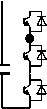 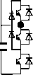  -a- -b- -c- FIGURE 26.5 MV stack topologies [3]. 26.6.3 Control Strategies Several control techniques can be found in the VSD industry, (refer to Fig. 26.6) these include: Open-loop inverter with fixed V/Fiz control Open-loop inverter with flux vector control Closed-loop inverter with flux vector control (induction motor) Direct torque control Table 26.15 summarizes the main features, advantages, and disadvantages of each technique [11]. 26.6.4 Communication in VSDs The use of a high-speed advanced digital communication (Fieldbus) to build industrial automation system for realtime TABLE 26.14 Comparison between different MV converter stack topologies Topologies Advantages Disadvantages 2-level with series devices (SC2L) 3-level NPC (3LNPC) Diode clamped multilevel (DCML) Capacitor clamped multilevel (CCML) Series-connected isolated h- bridges (ISHB) Simple and proven technology Same converter design over supply voltage range Standard fully developed PWM control Provision for series redundancy of power switches per inverter phase arm {n-\-I) Well proven Reduced harmonic content Better utilization of switches Reduced dV/dt (half the SC2L equivalent) Reduced harmonic contents Reduced dV/dt This configuration has all the advantages of a multilevel converter plus: Simpler arrangement, modular building block Fewer components Snubberless operation is possible Easier capacitor voltage balance than 3LNPC Modular design of the converter power modules The basic building block is based on a dc supply bridge, decouphng capacitor and a H-bridge arrangement In the ac supply the combined diode bridge rectifiers act like a multipulse bridge (18p for 4-level and 24p for 5-level), reducing harmonic injection into the ac supply Its output has very low harmonic content in spite of the low switching frequency Static and dynamic voltage sharing of series devices High dV/dt due to synchronous commutation of series devices High switching frequency harmonic content in inverter o/p voltage Series redundancy is difficult to achieve More complex PWM control is needed than 2-level Requires extra clamping diodes Requires split dc link Requires midpoint voltage balance control Even number of power devices per arm is always needed Switches require snubbers Series redundancy is very difficult to achieve Very complex PWM control is needed Requires many steering diodes Requires split dc link Requires voltage balance control of split dc link capacitors Uneven current stresses on power devices Requires snubbers Possible parasitic resonance between decoupling capacitors Complex to provide series redundancy More complex PWM control strategy than for 2-level Voltage redistribution of capacitors during supply voltage surges Too many capacitors (bulky stack design and poor capacitor utihzation at high ratings) Complex converter arrangement (for low stray inductance) Inverter rating is limited by the load current flowing through the capacitors Employs a special (bulky and expensive) transformer Complex to achieve series redundancy Different supply transformer designs are required for applications operating at different ac hne voltages Power pulsation for poor power factor loading Poor utihzation of capacitors Not suitable for common dc bus applications Dynamic Braking difficult 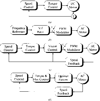 FIGURE 26.6 Electrical drive control techniques, (a) DC drive; (b) Frequency Control (PWM scalar control); (c) Flux Vector Control (Field-oriented control); (d) Direct Torque Control. control or simply for data logging has become well established in modern industries. Digital communication resulted in replacing wiring looms with a digital serial network; this resulted in a lower cost installation and more reliable solution. Over the past few years many industrial fieldbuses emerged, and end-users, system integrators, and original equipment manufacturers (OEMs) chose the optimum system for their applications. A fieldbus is a digital communication system that allows a control system to exchange data with remote sensors, actuators, and drives using a single communication hnk. The major benefits seen are reduced installation and cabling cost, and better overall immunity of the system. Both factors result in more reliable operation and reduced maintenance costs. There exist two main types of network: (a) Centralized network. Requires a network master controller, typically a PLC. The master device is entirely responsible for controlling communications over the network, while the slave devices tend to be dumb devices with no local intelligence. (b) Decentralized network. Requires some local intelligence at each node, but no overall master device. This is ideal for realtime application environments, as all nodes are effectively running in parallel. TABLE 26.15 Comparison between various control methods used in VSD
1 ... 62 63 64 65 66 67 68 ... 91 |
|
© 2026 AutoElektrix.ru
Частичное копирование материалов разрешено при условии активной ссылки |