 |
 |
 |
| Главная Журналы Популярное Audi - почему их так назвали? Как появилась марка Bmw? Откуда появился Lexus? Достижения и устремления Mercedes-Benz Первые модели Chevrolet Электромобиль Nissan Leaf |
Главная » Журналы » Metal oxide semiconductor 1 ... 63 64 65 66 67 68 69 ... 91 Most modern VSDs are equipped with hardware and software that enable local and remote communication with plant automated system via a fieldbus system. The most popular fieldbuses are Profibus, Interbus, Worldfib, and Devicenet. 26.6.5 PWM Techniques Different PWM techniques have been employed in PWM VSD converters. Figure 26.7 identifies the most commonly used techniques. 26.6.6 Impact of PWM Waveform 26.6.6.1 PWM Voltage Waveform Fast switching of IGBTs (typically < 1 is) results in high dv/dt, typically 3-5kV/is, and possible voltage overshoot at turn-off that can last for a few microseconds. The fast rate of rise/faU of voltage combined with high peak voltage at the turn-off results in a premature failure of motors as well as EMC. References [12-14] deal with the effect of PWM waveforms of VSD. The following is a brief summary of the effect of the unfiltered waveforms. 26.6.6.2 Effect on Motor Premature insulation failure due to partial discharge as a result of peak voltage, high dV/dt and high frequency Motor shaft voltage, which forces current into the shaft bearing, leading to early bearing failure Motor stray capacitance (between windings and earthed frame) leading to earth-current flow caused by high dV/dt High dv/dt creating nonuniform distribution of voltage across the winding, with high voltage drop across the first few turns and consequential failures In a large motor, voltage differential on the frame that is likely to develop in spite of protective earthing of the motor; more than one earthing point is needed 26.6.6.3 Effect on Cables Voltage doubling effect at the rising/faUing edges of voltage waveform due to wave propagation in long cables [12] Earth-current flows in cable stray capacitance due to dV/dt Restriction on cable type used and earthing methods employed Cable type (armored, screen, multicore) Likelihood of crosstalk with other surrounding cables running in parallel For PWM drives, cost of cabhng that is likely to be significant because of special requirements of cables, and termination methods employed 26.6.6.4 Effect on EMC/Insulation/Earthing Inductive and capacitive couphngs between live components and earth result in common-mode and differen- PWM Switching Strategies
Voltage-Controlled PWM Fixed Switching Frequency PWM Optimal & Harmonic I Elimination I Space Vector PWM I Conventional PWM
Sinusoidal Modulation Wave Natural Sampled I Modified Modulation Wave (Sinusoidal with addition of third Harmonic,trapezoidal, and other waveforms) Regular Sampled Asymmetric Modulation Symmetric Modulation FIGURE 26.7 Classifications of PWM techniques. tial-mode noise. This could lead to malfunctioning of nearby sensitive equipment. The voltage to earth applied on drive components pulsates at the switching frequency, adding voltage stresses (worst at low speeds, low modulation index). This poses additional insulation requirements on main power components (motor, cable, output filter, and transformer). A fourth wire may be required between the motor frame and the converter virtual earth so that a low-impedance path is provided for the motor earth current. Strict rules must be observed when cabhng and earthing. 26.6.6.5 Motor Insulation High peak voltages can be experienced at the motor terminals, especially when long cable is employed (10-100 m depending on the size of motor). This is usually caused by voltage-doubling phenomena of a transmission line with unequal line and load impedance. Motor-line voltage can reach twice the dc link voltage with long cables. Fast voltage rise times of 5000 V/is can be measured at the motor terminals. Under these conditions, the motor insulation becomes stressed and can lead to a premature breakdown of a standard motor insulation. When the motor fails as a result of insulation stress caused by high peak voltage and fast voltage rise times, failure occurs in the first turn as phase-to-phase short or phase-to-stator short. The highest voltage is normally seen by the first turn of the winding. Standard motor capabilities, established by the National Electric Manufacturers Association (NEMA) and expressed in the MG-I standard (part 30), indicate that standard NEMA type В motors can withstand 1000 V peak at a minimum rise time of 2 is (500 V/is). Reference [13] describes the effect of PWM inverter waveforms on motor insulation in more detail. 26.6.6.5.1 Partial Discharge The phenomenon that starts deterioration of the motor insulation is called partial discharge (PD). When electric stresses in insulation voids exceed the breakdown voltage of the air, a partial discharge occurs. Successive PDs destroy the insulation slowly. 26.6.6.5.2 Voltage Strength, Phase-to-Phase and Phase-to-Frame Both NEMA and lEC are proposing (a) maximum 1000 V at rise time less than 2 is and (b) a maximum rate of rise of 500V/is. It is beheved that low-voltage standard motors can withstand much larger voltage stresses than specified by NEMA and lEC, possibly up to 1300 V, almost regardless of the rise time. 26.6.6.5.3 Voltage Strength, Turn-to-Turn In low-vohage ac motors, the conductor insulation is designed for 245 V RMS (350 V peak). The insulation strength, however, is higher depending on the impregnation method. 26.6.6.6 Bearing Current Bearing current and shaft voltages under 50/60 Hz sine-wave operation has been recognized since 1924. The bearing impedance characteristics largely determine the resulting bearing current that will flow for a given shaft voltage [14]. The rotating machines have three basic sources of shaft voltage: Electromagnetic induction from the stator winding to the rotor shaft (due to small dissymmetries of the magnetic field in the air gap that is inherent in a practical machine design. The design limit is < 1VRMS. Electrostatic coupled from internal sources. Such a voltage in motors where rotor charge accumulation may occur (belt driven coupling, ionised air passing over rotor fan blades). Electrostatic coupled from external sources such as PWM inverter. The presence of high dV/dt across the stator neutral to frame ground causes a portion of the voltage to ground due to capacitor divider action. The presence of PWM related voltage component is undesirable and lead to a premature bearing failure. The fundamental cause of the shaft voltage is magnetic dissymmetry between the stator and the rotor or possibly a phase shift of the motor voltage waveform. System ground may also contribute to this condition through unbalance system voltage. NEMA-500 recommends the consideration of insulated bearing for motor frame of certain sizes. 26.6.6.7 EMI The main sources of electromagnetic interference (EMI) of PWM VSI drives are described in reference [15] as follows: ac/dc converter. Supply harmonics caused by supply bridge rectifier (100 Hz-2.5kHz). As already explained, the input bridge circuit with an SCR or diode bridge is a source of supply harmonics in the input current. dc/ ac inverter. Harmonics caused by the switching of the inverter bridge (3 kHz-20 MHz). The inverter bridge uses fast switching devices to create PWM voltage output. The inverter is a source of a wide band of frequencies, typically extending from the basic switching frequency (several kilohertz) to the radio high-frequency bands at 20 MHz. The radio-frequency current spreads out into both the supply and motor connections. An EMC filter is often used to hmit spread of high-frequency harmonics into the supply. Control electronics. The control circuit employs a microprocessor with clock frequency of several megahertz, typically 20 MHz. The clock wave produces frequencies that are muhiples of 20 MHz up to 300 MHz. Table 26.16 summarizes main techniques used to overcome problems associated with EMI at source as well as at load. Effect Frequency Range Countermeasure At Source At Load
26.6.7 Techniques Used to Reduce the Effect of PWM Voltage Waveform 26.6.7.1 Output Line Reactor A reactor increases the rise time but the benefit of its connection may be negated as foUows: Beneficial connection if cable length is short enough for reflections to be superimposed within rise time, i.e., if rise time is increased beyond critical value of cable length FLarmful connection if cable length is too long; the reactor may have negligible effect on peak voltage (theoretically its presence is insignificant in this case) or ringing period, but it wiU increase the duration of each overshoot, thus increasing the probabUity of partial discharge Adding a series line reactor between the motor and inverter is not as simple as illustrated previously, because the reactor adds or adjusts other resonant modes where the reactor rings with lumped capacitances. These resonant modes are pure transmissions line modes and can double voltage. Some line inductance helps short-circuit protection. If earth current is limited by other means, then the coupled reactors may be helpful. 26.6.7.2 Sine-Wave Filter This mechanism filters the PWM carrier frequency; thus, the converter output voltages are sinusoidal. This type of filter is best suited for low- performance drives and/or retrofit applications (old or standard motors). Reference [16] and Table 26.17 illustrate the filtering options for high-power VSDs. Employing a filter at the inverter output has some practical consequences: Cost and weight of converter increase Filter power losses, voltage drop across filter inductance A smaU derating of power switches due to circulating current between filter L, C, and dc link capacitor Reduced torque response due to time delay in the filter, sine-wave type Potential osciUations that have to be electronically dampened Potential induction motor self-excitation
First published in Power Engineering Joumal, Feb. 2000, Vol. 14, No. 1, pp. 12-20. Used with permission, ©2000, lEE. TABLE 26.16 Overview of techniques used as a countermeasures to EMI [15] 26.6.73 PWM {dV/dt) Filter This reduces the dV/dt seen by the motor to a level that does not compromise the motor or EMC. It is ideal for high-performance drives with custom-built motors. 26.6.7.4 RC Filter at Motor Terminals A simple RC network is used at the motor terminal; the capacitor would represent a short circuit for the high-frequency components (sharp dV/dt). Wave reflection will not happen if the resistor value is similar to the cable characteristic impedance. Resistor losses are generally small, as current flow will only occur at the rising and falling edges of the PWM waveform. (I) PWM VSI with a diode supply front end (II) As above, but with a dynamic brake chopper (III) Fully controlled thyristor front end (IV) As above, but with a dynamic brake chopper (V) Fully controlled antiparallel thyristor supply bridge (VI) PWM supply front end The use of a higher pulse number than 6-pulse would necessitate the use of a supply transformer. This is always considered to be an unnecessary evil because of additional cost, losses, and the need for extra space to accommodate this component. For MV apphcations, this is considered to be a necessity for isolation and protection. 26.6.7.5 Common-Mode Reactor The presence of capacitive current due to the high dV/dt can be improved by employing a common-mode reactor. It is well established that such a choke is not effective in reducing the RMS and mean values of the leakage current, but only effective in reducing the peak value. The presence of such a choke in the circuit increases the inductance and resistance of the zero sequence impedance. 26.6.8 Supply Front End For PWM VSI Drives There are many types of PWM voltage source drive depending on the supply front-end type and regenerative technique employed (Table 26.18): 26.6.8.1 Regenerative Braking Several techniques are usually used for regenerative braking. A simple diode front-end supply bridge will operate in two quadrants (positive and negative speeds). There is no regenerative power capability, as any regeneration of power would result in an increase in the dc link voltage, and the drive will trip on overvoltage. If a small amount of regeneration is required, during stopping or speed reversal, then a dynamic brake chopper may be used. This is a simple chopper with a dynamic brake resistor. The size of the resistor is very much dependent on the regenerative brake energy, its magnitude, and its repetition rate.
Full-power regeneration is possible by employing a fully controlled antiparallel thyristor front end. This is similar to that used on dc drives or cyclo converters. A more modern approach is to use a pulse converter front-end (fully controUed bridge). This is a four-quadrant converter with the abUity to control the power factor and the dc link. Such an option necessitates the use of a precharge circuit for the dc hnk, and smoothing inductance on the ac side. For fully regenerative drives, the supply needs to be receptive. By using a PWM rectifier as a primary converter in this composite structure, both the problems of regeneration and line current distortion are successfully solved - with the penalty of having a much more complicated converter structure and control system. With modern PWM VSI VSD controUer, the supply bridge can be fully controUed. Such an option offers the foUowing benefits: 26.7 Applications 26.7.1 VSD Applications Table 26.19 summarizes main industries and applications. Present solutions for drives, and electric drive apphcation examples from various industries have been described in this section. 26.7.2 Applications by Industry 26.7.2.1 Deep Mining Reference [17] hsts various high-power MV VSI inverter drive applications for the mining industry. In deep-mine conveyor-belt applications, a PWM VSI drive offers significant advantages over other conventional alternatives. The foUowing benefits have been identified for deep-mine conveyor-belt applications: Improved drive starting and stopping
The PWM VSI drives can also be used to replace dc and cyclo-converter drives for mine hoist apphcations. The benefits are as follows: Improved drive control, with 100% continuous stall torque available with induction motors Reduced ac supply disturbances Very little need for reactive MVAR correction even at high ratings Improved immunity to ac supply dips The use of electrically coupled mine-hoist systems has many advantages, especially for deep mines, and is set to become an essential feature of many new mine-shaft systems. The circuit is shown in Fig. 26.8. The power flows naturally from motor 1 to motor 2 such that at the point of balance the ac supply current is virtually zero and at near unity power factor. This technology is the natural successor to the dc electrically coupled winders and totally solves the poor ac power factor that would result if twin-drive cyclo motors were used. 26.7.2.2 Industrial Processes In the industry, there are a number of viable drive solutions available for the major-market power ranges, from LCIs to FCI. However, there is a developing market for MV variable-speed drives. The PWM VSI using new high-power IGBTs or IGCTs appears to be the best solution for the future. Benefits include better power factor, no limit on frequency, and higher voltages. PWM VSI converter cost is likely to be higher than that of other equivalent well-established technologies (e.g., LCI). Hence, the flexibility in choice of motors and improved control must be exploited. The advantage of offering an MV solution may prove significant. Possible means of reducing motor costs are as follows: 1. Higher frequencies are achievable, allowing the use of high-speed motors and gearboxes. 2. Higher pole number machines can be used, giving cost savings. 3. Power factor is better over the speed range, giving power-supply savings. 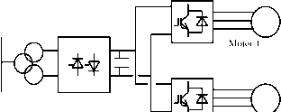 12 pulse supply converter Motor 2 FIGURE 26.8 PWM-VSI electrically coupled mine hoist drive. 4. Induction motors with rotors adapted for use with VSDs can be used with resultant cost savings over standard DOL, fixed-speed motors. 5. Voltages are higher and conductors smaller. However, at low powers the relative cost of the machines is less significant versus the cost of the converters. Hence, the viability of this technology in this market requires close examination. The cyclo-converter drive with a synchronous motor is used when four-quadrant operation is required, particularly drive requirements are high power rating with high torque at low speed and at standstill but with a rather low maximum speed. Gearless cement mill drives were the first applications of cyclo converters. The mill tube is driven from a low-speed wrap around motor with a high number of poles. 26.7.2.3 Metal Industry The majority of installed hot-mill drives are cyclo converters. A few LCI drives have been used, but applications are limited for such technology on mill main drives. Most early-generation plants are equipped with dc drives. The trend is to replace dc with ac. Direct current drive applications were universally used in the first generation of rolling mills. The market for new mills requiring this technology is declining as the steel industry moves to ac as a preference. On early-generation mills where motors are retained, dc drives are likely to be required. In their enquiries, some customers request ac alternatives, but others are still requesting dc drive solutions. Dc drives are probably still the most economic for the power range 750 to 1500 kW. The number of manufacturers producing dc motors, however, is declining, particularly large dc motor manufacture. The lower price of dc solutions is offset by the advantage of use of ac motors in ac solutions, making ac the more popular choice. Current-source inverter LCIs can be applied to roughing stands of rod and bar Mills. Technical hmitations include the risk of torque pulsation and a minimum drive output frequency of 8 Hz. The cyclo converter is the solution most often used. However, it is relatively expensive compared to alternative technology. Major cost penalties arise from supply transformers, cabling, and bridge configurations. In some cases, active power-supply compensation equipment may be required, taking the costs even higher. Cyclo-converter solutions will still be cost effective for medium- to high-power, low-speed, low-frequency (say below 21 Hz max operating frequency) applications. This would include hot reversing mills, with direct drive, for the primary rolling processes, albeit a dechn-ing application area, and possibly for direct-drive, low-speed, high-torque roller-table apphcations. Technical limitations include limited output frequency (typically 29 Hz for 12-pulse, at 60-Hz supplies), which can necessitate the use of two-pole motors to reach application speeds. The high-power PWM VSI using new power devices (IGBT/IGCT) appears to be the best solution for the future. Benefits include better power factor, no limit on frequency, and higher voltages. Potentially either the two-level or the multilevel solution wiU meet the market requirements. In some applications, such as coilers/uncoilers, the system is composed of several drives, which have different power cycles, when some drives are furnishing power and other are braking. A common dc bus system wiU aUow the energy fed from drives operating in the regenerative braking mode to be utilized by other drives connected to the same dc bus, but operating in the motoring mode. The supply bridge, i.e., rectifier, feeding the dc bus system will only be rated for the total system power. The benefits of dc bus systems include the following: Good operating power factor Low harmonics (lowest when using 12-pulse or 18-pulse front ends) Possibility of energy transfer on the common dc link solutions (reducing front-end converter and transformer sizes with attendant energy savings; possibility of using kinetic energy to aUow controlled stopping) 26.7.2.4 Marine and Offshore Drive powers are commonly in the range of 0.75 to 5.8 MW for thrusters, and 6 to 24 MW for propulsion. The evolution in the commercial market is toward powers from 1 to 10 MW for propulsion. Higher powers are required for naval applications with package drive efficiency better than 96%. PWM inverters at these powers would allow the use of induction machines, rather than the more expensive synchronous alternatives required for LCI drives. This could provide savings in the price of the motor. Current-source inverter drive LCI is used for aU applications except for icebreakers, where cyclo-converter drives are used. The PWM (voltage source) inverter using new force-commutated drives appears to be the best solution for the future. Benefits include better power factor, no limit on frequency, and higher voltages. Many ice breakers and some other ships are equipped with diesel-generator-fed cyclo-converter synchronous motors with power ratings up to about 20 MW per unit. 26.7.3 Examples of Modern VSD Systems 26.7.3.1 Integrated Power System for All-Electric Ship This is a fuU-scale main propulsion drive for the U.S. Navy [18]. It consists of a main-propulsion 19-MW induction-motor drive system. The power converter consists of three 6-pulse rectifier stages, three 6-kV dc hnks, and 15 IGBT-based H-bridges feeding a 15-phase induction motor (Fig. 26.9). This drive demonstrates the potential of modern power electronics over more traditional solutions such as cyclo converters and LCIs. The volumetric power density of the : 6 pulse diode I bridge 21MW generator
A single dc bus, 6kV ! DC, feeding 5xHbridges.!  15 phase, 19MW induction motor Passive 5 harmonic filter FIGURE 26.9 Schemaric diagram of the IPS drives system [18]. new converter is reported to be 905kW/m, compared to 455kW/m for cyclo and 313kW/m for LCI. 26.7.3.2 Subsea Separation and Injection System This is a fuU-scale pilot plant developed to increase recovery and improve the economics of offshore oil and gas fields. The system comprises several VSD units, typically 500-kW oil pump. 1 MW multiphase booster, and 1-2.5 MW water injection drive unit; such a system is called SUBSIS [19]. The main task for such a system is to separate the bulk water from the weU stream and treat it either for discharge into the sea or reinjection into the reservoir. This system employs subsea-based rotating machinery for pumping, boosting, and compression. The Subsea Electrical Power Distribution System (SEPDIS) provides innovative and cost-effective subsea processing (Fig. 26.10). The pump motors are mounted in a pressurized vessel and positioned on the seabed. Reference [19] identifies the benefits of subsea drives as foUows: Three to six percent increase in oU and gas recovery Improved pipeline transportation conditions by removing water from the weU stream Reduced environmental impact due to lower energy consumption and reduction in chemicals used to inhibit corrosion Reduced size and cost of new platforms Cost-effective development of marginal fuels through reuse of existing infrastructure 26.7.3.3 Shaft Generator for Marine Application During cruising at sea, up to 3.5 MW of electric power is extracted from the ships main diesel engine/propeUer shaft (90,000 hp per ship) via a salient pole shaft generator, which is fitted to the main propeUer shaft. The converter output voltage (set at 60 Hz) is stepped up to 6.6 kV [20]. HV AC bus X ACCB 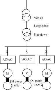 Oil pump 500kW FIGURE 26.10 Schematic diagram of SEPDIS [19]. The converter is based on 24-pulse-converter (LCI) technology, which is traditionally used as main ship propulsion. The shaft generator output frequency varies between 14 and 25.7 Hz, 6-phase generator and the output stage is configured as 24-pulse, via a step-up transformer. At the output a passive LC filter is employed, with a synchronous condenser, started by a pony motor. This type of application is likely to significantly benefit from the higher volumetric power density of the PWM VSI with 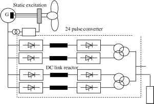 6.6kV,60Hz AC in: 14-25.7hz Harmonic filter & Pony motor MG FIGURE 26.11 Schematic diagram of shaft generator [20]. fully controlled front end. Such a system will eliminate the need for a passive filter at the output stage, and will use a standard three-phase generator. The same technology is also applicable to high-speed generators and windmill energy. The ability of the active front end to sustain fixed dc link voltage over a relatively wide shaft speed range results in a very good control of the output voltage, irrespective of the shaft speed. In wind power plants, the optimal efficiency of the wind turbine depends on the speed when the wind conditions change. It is, therefore, advantageous to vary the speed of the generator and link it via a frequency converter to the ac system. For high-speed generators, driven by diesel engines or gas turbines, the fully controlled converters enable direct power conversion from ac high-frequency (hundreds of hertz) to fixed power frequency (50/60) Hz fixed output voltage. The magnitude of the output voltage is kept constant irrespective of speed variation on the generator speed. 26.7.3.4 Linear Motor Drive for Roller Coaster This drive involves a fully regenerative PWM VSI. The supply front end is made of antiparallel thyristors; the machine bridge is based on PWM IGBT VSI. The Escape has been developed for Six Flags California at Magic Mountain. The inverter output frequency is 0-230 Hz, and 525 V ac RMS. The power rating is 1.8 MW. The duty cycle is 1.8 MW for 7 seconds, followed by 16 seconds at zero power, and 1.3 MW for 5 seconds and a stop period of 32 seconds. This ride involves acceleration at 4.5 g, speed, and free fall (6.5 seconds of weightlessness, during which a height of 415ft is achieved [21]). The same concept employed in this application could be used for airplane launchers on aircraft carriers, instead of the conventional catapult. 26.8 Summary The benefits of VSD are there to be quantified, and energy savings have been the prime reason for employing a VSD in stand-alone drive applications. Other benefits such as improve process control or increase life expectancy are often difficult to quantify in real terms. There is a large selection of VSD systems to meet a wide range of applications. At low and medium power, the induction motor and PWM VSI are supreme. At higher power ratings, MV PWM VSIs are gaining popularity, but LCI and cyclo-converter drives would remain key technologies with very high-power applications. Modern drives are becoming more available at competitive prices with good rehability records. However, there are concerns with regard to the impact of fast switching on the motor and the environment. To ensure successful implementation of VSD system, both the supplier and end users need to work in partnership. Ideally, one competent supplier should supply the full drive package, with some after-sale service support. Understanding the nature of the load plays an important role in specifying the power rating of VSDs correctly to meet performance requirements and required life expectancy. New areas of VSD applications are emerging as power electronics advances and become more reliable at affordable prices. Packaged drive up to several hundred kilowatts are becoming a commodity product, and end users do not need to involve a third party during specification, installation, and commissioning. Integrated motors are likely to increase in popularity, possibly with new types of power converters, e.g., matrix. References 1. Dury, W., Electrical variable speed drives mature consumable or radical infant, Power Engineering Journal, April 1999, Vol. 13, No. 2. 2. Guide to Harmonics with ac Drives. ABB Technical Guide No. 6. 3. Shakweh, Y., Power devices for MV PWM VSI converters, Power Engineering Journal, Dec. 1999. 4. Richmond, A. W., A Practical Engineers Handbook, Industrial Electric Drives, Drives & Controls Publications, Kamtech Publishing Ltd., Croydon, Surrey, UK. 5. Siemens, Complete Guide Series to Variable Speed Drives, Knowledge of Motor Duty - Key to Proper Planning of Drives, 3.6. 6. Hobbs, P. J., Electrical variable speed drive saves energy, Conference on Development in Variable Speed Drives for Fluid Machinery, ImechE 1981, ClOl/81. 7. Bose, B. K., Power Electronics and Variable Drequency Drives: Technology and Applications, IEEE Press, Piscataway, NJ, 1997. 8. Richmond, A. W., Apprentice Engineers Handbook, No. 2, Servos and Steppers, Drives and Controls Publication, Kamtech Publishing Ltd., Croydon, Surrey, UK. 9. Shakweh, Y., Aspects of Limited Motion Actuators and Sub-kW Unipolar Drives, Ph.D. thesis, Aug. 1989, London University. 10. Shakweh, Y, and Lewis, E., Assessment of MV converter stack topologies, Power Electronics Specialist Conference 99. 11. Direct Torque Control, ABB Technical Guide No. 1. 12. Jouanne, A. V, Enjeti, P., and Gray, W., Application issues for PWM adjustable speed ac motor drives, IEEE Industry Application Magazine, Sept/Oct 1998, pp. 10-18. 13. Manz, L., Motor insulation system quality for IGBT drives, IEEE Industry Application Magazine, Jan/Feb 1997, pp. 51-55. 14. Chen, S., and Lipo, T. A., Circulating type motor bearing current in inverter drives, IEEE Industry Application Magazine, Jan/Feb 1998, pp. 32-38. 15. Hargis, C, Electro-magnetic Compatibility-A Basic Guide for Power Engineers, Control Techniques Technical publications, Powys, UK. 16. Shakweh, Y, and Aufleger, P., Multi-megawatts, medium voltage, PWM voltage source sine-wave converter for industrial drive applications, Power Electronics & Variable Speed Drives Conference (PEVD98), UK, London, 21-23 Sept. 1998. 17. Shakweh, Y, Lewis, E. A., and Gent, A., High-power drives for mining applications, Minmech 98, South Africa, Sept. 1998. 18. Crane, A., and McCoy, T J., EMC Design for a 19-MW PWM Motor Drive. 1999 IEEE Industry Applications Society Annual Meeting99, Vol. 3, pp. 1590-1995. 19. Stromquist, R., and Gustafson, S., SUBSIS - Worlds first separation and injection system, ABB Review, June 1998. 20. Clegg, В., Hall, D. J., and Tavner, R J., The application of drives and generator technology to a modern container ship, lEE, PEVD98, London, UK. 21. Elliott, N. J., Novel application of a linear synchronous motor drive, lEE Colloquium on Update on New Power Electronics Techniques, lEE, London, 23 May 1997. Table of abbreviations BDCM - brushless dc motor CCML - capacitor clamped multi-level CSI - current source inverter DCML - diode clamped multi-level DOL - direct on line EMC - electromagnetic compatibility EMF - electro-motice force EMI - electromagnetic interference FCI - forced commutated inverter GTO - gate turn-off thyristor IGBT - insulated gate bipolar-transistor IGCT - integrated gate commutated thyristor ISFLB - isolated series FL-bridge LCI - load commutated inverter LIM - linear induction inverter LSM - linear synchronous motor LV - low voltage MMF - magneto-motive force MV - medium voltage NPC - neutral point clamp OEM - original Equipment Manufacturer PLC - programmable logic control PM - permanent magnet PWM - pulse width modulation SC2L - series connected 2 level SRM - switched reluctance motor 3LNPC - 3 level neutral point clamp VSD - variable speed drive VSI - voltage source inverter 1 ... 63 64 65 66 67 68 69 ... 91 |
|||||||||||||||||||||||||||||||||||||||||||||||||||||||||||||||||||||||||||||||||||||||||||||||||||||||||||||||||||||||||||||||||||||||||||||||||||||||||||||||||||||||||||||||||||||||||||||||||||||||||||||||||||||||||||||||||||||||||||||||||||||||||||||||||||||||
|
© 2026 AutoElektrix.ru
Частичное копирование материалов разрешено при условии активной ссылки |