 |
 |
 |
| Главная Журналы Популярное Audi - почему их так назвали? Как появилась марка Bmw? Откуда появился Lexus? Достижения и устремления Mercedes-Benz Первые модели Chevrolet Электромобиль Nissan Leaf |
Главная » Журналы » Metal oxide semiconductor 1 ... 66 67 68 69 70 71 72 ... 91 Fig. 27.32. The stator per phase resistance R is now included in the analysis. The developed torque is then given by ЯХ sin + R{ cosS - Nm (27.63) for the nonsalient-pole motor and -fR+ VEfjX, sin S +-(X, - X,) sin 23 - VREf, cos 3 RLXX X Nm (27.64) for the salient-pole motor, where the subscript о refers to base quantities and Я refers to the per unit input frequency f . Equations (27.63) and (27.64) indicate that the maximum torque that the motor can develop diminishes at low speed because of the voltage drop across the stator resistance R. This drop in maximum available torque at low speed can be avoided by boosting the input vohage at low speed, as indicated in Fig. 27.33a. This voltage boosting is similar to the IR compensation apphed to a variable-frequency induction motor drive. Figures 27.33 indicate an open-loop V-f inverter drive scheme, similar to the same scheme for an induction motor drive in which the RMS stator input voltage is made proportional to frequency. The speed reference is passed through a first-order filter, as shown in Fig. 27.33a, so that a large and speed reference 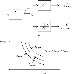 abrupt change in the input frequency command to the inverter is avoided. The filtered speed reference is translated into a proportional frequency reference f. The voltage reference V is also proportional to frequency reference, but with a zero frequency bias. The variable RMS input voltage V to the motor may be obtained from an inverter by SPWM methods or from a cycloconverter with phase angle control. The available input voltage V is normally limited by the available dc-link voltage to the inverter or the ac supply voltage to a cycloconverter. This limit is normally arranged to occur at base speed. Above this speed, the stator flux drops, leading to field weakening and constant-power-like operation, as indicated in Fig. 27.33b. In some control schemes, the maximum load angle 3 is not aUowed to exceed a certain limiting value jax- By selecting 3, constant-power operation at various power levels is possible. 27.4.4 Characteristics under Current-Source Inverter (CSI) Drive A current-source-driven synchronous motor drive generally gives higher dynamic response. It also gives better reliability because of the automatic current-limiting feature. In a variable-speed application, the synchronous motor is normally driven from a stiff current source. A rotor position sensor is used to place the phase current phasor / of each phase at a suitable angle with respect to the back emf phasor (Ef) of the same phase. The rotor position sensor is thus mandatory. Two converter schemes have generally been used. In one scheme, as indicated in Fig. 27.34, a large dc-link reactor (inductor) makes the current source to the inverter stiff. The scheme is suitable for large synchronous motors for which thyristor switches are used in the inverter. A current loop may also be established by sensing the dc link current and by using a closed-loop current controUer that continuously regulates the firing angle of the controUable rectifier in order to supply the inverter with the desired dc-link current. It can be shown that the motor-developed torque is proportional to the level of the dc-link current. The inverter drives the motor with quasi-square-wave current waveforms as indicated in Fig. 27.35. The current waveforms are switched according to measured rotor position information, such that the current waveform in each phase has a fixed angular displacement, 7, with respect to the induced emf of the corresponding phase. Because of this, the drive is sometimes referred to as self-controlled. The angular displacement of these current waveforms (or their fundamental components) with the respective back emf waveforms is indicated in Fig. 27.35. Because of the large dc-link inductor, phase currents may be considered to remain essentially constant between the switching intervals. The quasi-square current waveforms contain many harmonics and are responsible for large torque pulsations that may become troublesome at low speed. INVERTER AC Mains -  ins f I DC-Link current controller + DC-Link -DC-Link -7 Г  FIGURE 27.34 Schematic of a current-source-inverter-driven synchronous motor. In the foregoing scheme, the motor can be reversed easily by reversing the sequence of switching of the inverter. It can also be braked regeneratively by increasing the firing angle of the input rectifier beyond 90° while maintaining the dc-link current at the desired braking level until braking is no longer required. The rectifier now returns the energy of the overhauling load to the ac mains regeneratively. In another scheme, which is preferred for lower capacity drives for which higher dynamic response is frequently sought, phase currents are regulated within the inverter. The inverter typically employs gate turn-off switches, such as the IGBT, and pulse-width modulation techniques, as indicated in Fig. 27.36. Motor currents are sensed and used to close independent current controllers for each phase. Normally, two current 120 > laref  Ibref  Icref  AC supply ~  + DC-Link - DC-Link laref href Icref Sinusoidal Current References (iaref ibref& icref) LOOK UP TABLE X л -i< S -i< s 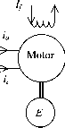 FIGURE 27.36 Control scheme of the SPWM current-source drive. controllers suffice for a balanced star-connected motor. Three-phase sinusoidal ac currents are supplied to the motor, the amplitude and phase angle of which can be independently controlled as required. The references for the current controllers are obtained from a three-phase current reference generator that is addressed by the feedback of the rotor position. The rotor position is continuously measured by a high-resolution encoder. In this way, the current references, and hence the actual rotor currents, are synchronized to the rotor. 27.4.5 Brushless dc Operation of the CSI Driven Motor The torque characteristic of the CSI drive scheme of the foregoing section can be easily analyzed using the phasor diagrams shown earlier if the harmonics in the motor current waveform are neglected or if the motor current waveforms are indeed sinusoidal as in the second scheme described earlier. In the following analysis, it is assumed that the supply current waveforms are sinusoidal. It is also assumed that the phase angle of these current sources with respect to the induced voltage in each phase can be arbitrarily chosen. The phase back-emf and the current waveforms and the phasor diagram of the nonsalient-pole motor are shown in Fig. 27.37. The phase angle 7 between the Ej: and / phasors and the rms value (or amplitude) of / are determined according to the desired torque and power-factor considerations. The developed torque is found from the phasor diagram to be T = - 3EjrI cos 7 = Кф1со8у Nm (27.65) If the angle 7 = 0° is chosen, the familiar dc-motor-like torque characteristic is obtained. It should be noted from the foregoing that the developed torque at any speed is independent of R since a high gain (stiff) current source drive is used. Note also that the ratio at any operating speed is proportional to the amplitude of the stator flux linkage, due to rotor excitation. For fixed rotor excitation this ratio is a constant. Equation (27.65) indicates that the developed torque of a nonsalient-pole synchronous motor can be controUed by controUing the amplitude of the rotor field (field control) or, more conveniently, by controUing the amplitude of the stator phase current. The highest torque-per-ampere characteristic is achieved when 7 = 0°. Note that operation with a fixed 7 angle is key to this dc-motor-like torque characteristic. 27.4.5.1 Operation with Field Weakening If the stator impedance drop is neglected, the maximum Ef is largely determined by the dc-hnk voltage and, Ef = кХо) imphes that speed ш can be increased by decreasing Я^. Consequently, operation above base speed is normally achieved with field weakening. In this speed range, because of the limited dc-hnk voltage, the rotor field must be
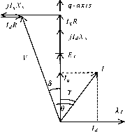 d-axis -> FIGURE 27.37 Phasor relationships of CSI-driven motor: (a) back emf and current waveforms; (b) the phasor diagram. weakened; otherwise, the amplitude of the phase-induced emf will exceed the dc-link voltage and current control will not be effective. Field weakening is a means of keeping this voltage at the rated level for speeds higher than the base speed. The flux linkage due to the rotor excitation, Я^, can be adjusted when a variable rotor supply is available. This may also be achieved by demagnetizing the rotor mmf by using the mmf produced by the stator currents. For motors with permanent magnet excitation, the latter is the only means of weakening the X. Referring to the phasor diagram of Fig. 27.38, if / is made to lead Ep the (i-axis component of /, i.e., /j, will lead E by 90°. The mmf due to 1 then opposes the rotor (i-axis mmf. The net rotor flux linkage along the -axis is then given by Я} = Я^ + 1Д (27.66) where 1 is negative when / leads E. If the airgap is small, the (i-axis component of the armature current may reduce the rotor flux to the required extent. q-axis 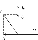 > d-axis 27.4.6 Operating Modes A synchronous motor may driven with various operating characteristics, such as with power factor compensation, with maximum torque per ampere and with field weakening. The power factor at which a synchronous motor operates is an important issue, especially for a large drive. A large angle 0 between the input voltage and current to the motor results in a poor power factor. Operation of the synchronous motor with a current source inverter allows interesting power factor compensation possibilities. Consider the following three cases. 27.4.6.1 Case A: Operation with I Lagging Ef In this case, the motor is underexcited and / lags by an angle 7, as indicated in Fig. 27.39. The overall power factor in this case is lagging, since / lags V by angle в. The power factor angle в is larger than y. Note that 1 now magnetizes the rotor field. 27.4.6.2 Case B: I Is in Phase with Maximum Torque per Ampere Operation (7 = 0°) If у = 0° is used, the motor input current is in phase with the back emf e, as indicated in the waveforms of Fig. 27.40a. From Eq. (27.65), the developed torque is given by Т = Кф1 (27.67) Thus, for a fixed rotor excitation, the developed torque is the highest that can be achieved per ampere of stator current /. In other words, if 7 = 0° is chosen, the drive operates with its maximum torque per ampere characteristic. From the phasor diagram of Fig. 27.40b, it is clear that the input current phasor / phasor now lags the voltage V phasor at the motor terminals, (see the phasor diagram below). Note that the level of Ep 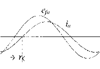 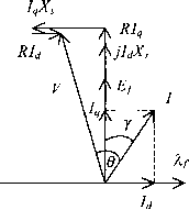 (a) (b) FIGURE 27.39 (a) Phase back emf and current waveforms and (b) the phasor diagram with / lagging E.
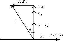 (a) (b) FIGURE 27.40 (a) Phase back emf and current waveforms and (b) phasor diagram for / in phase with Ej. which is determined by the level of excitation, also determines the angle д to some extent. Clearly, when maximum torque per ampere characteristic is required, a power factor less than unity has to be accepted. 27.4.6.3 Case C: Operation with I Leading If / is chosen to lead E the overall power factor can be higher, including unity, as is indicated in Fig. 27.41. Note that the motor now operates with less than maximum torque per ampere characteristic. Note also that the (i-axis component of / now tends to demagnetize the rotor and that operation with field weakening is implied. With a CSI-driven motor, the amplitude and the angle of the phase current relative to the back emf can be selected according to one of the desirable operating characteristics mentioned above. Additionally, other operational limits such as the inverter/motor current hmit, the maximum stator voltage limit, and the maximum power limit can also 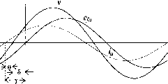 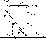 I leading E j FIGURE 27.41 Back emf and current waveforms and phasor diagram for / leading Ej-. COref +  LOOK UP TABLE & CURRENT PROFILER href + -> - /\ Href cref  N V E R T E R  FIGURE 27.42 Structure of a speed-control system with a CSI-driven synchronous motor. addressed. The amplitude of the stator current / clearly determines the developed torque of the motor. Consequently, the error of the speed controller is used to determine the amplitude of /. The overall control system with an inner torque loop may be described by Fig. 27.42. 27.4.7 Vector Controls The foregoing controls were based on the steady-state equivalent circuit of the motor. Even though the torque equation (27.65) for a current-source drive evokes vector-control-like relationships, they do not address the dynamics of the current controls as is possible in an orthogonal reference frame. Using an orthogonal set of reference attached to the rotor, a simple set of decoupled, dc-motor-like torque control relationships is readily obtained. Following the transformation technique used in Section 27.3.3, the stator voltage equations of a synchronous motor with fixed rotor excitation in the rotor reference frame are Note that Eq. (27.68) can be written down directly from (27.31), taking into account fixed rotor excitation so that the third and fourth rows and columns of Eq. (27.31) need to be dropped. Since the reference frame now rotates at the speed of the rotor, = CD. The induced back emf due to the fixed rotor excitation occurs in the rotor -axis and is included in (27.68) as a separate term. Similarly, the torque expression of (27.69) may also be written down from Eq. (27.41), using the flux linkages of Eq. (27.70). Equations (27.67)-(27.69) are for a sahent pole motor for which Ld Ф Lq. For a nonsalient-pole motor, L is equal to L and the developed torque is proportional to only. In either case, the inner torque loop consist of two separate current loops; one for and the other for i, as indicated in Fig. 27.43. The iq current loop generally derives its reference signal from the output of the speed controller and constitutes the inner torque loop. The reference for the i current loop is normally specified by the extent of field weakening for which a negative
CDlf T = -P(lfiq(Ld-Lq)idiq) (27.68) (27.69) where all the quantities in lowercase represent instantaneous quantities in the rotor dq-frame. is the flux hnkage per phase due to the rotor excitation, ш is the electrical angular velocity in rad/s, and P is the number of pole pairs, p is the time derivative operator djdt. Assuming magnetic hnearity, the stator flux linkages are d4 \ = Lqiq (27.70) -axis current controller J-axis current controller inverse d-q transformation INVERTER transformation  Inner torque loop of a vector-controlled synchronous reference is used. Otherwise, the d-axis current is maintained at zero. Note that for large synchronous motors with variable external excitation, field weakening is normally apphed through adjustment of the rotor excitation, using a spiUover signal from the output of the speed controller. From Eq. (27.68), it is clear that couplings of q- and d-axis voltages exist through the d- and -axis currents, respectively, and the back emf. During dynamic operation, such coupling effects become undesirable. The couphng effects of d- and q-axis currents and the back emf into q- and d-axis voltages, respectively, can be removed by the feed-forward terms shown in the shaded part of block diagram of Fig. 27.44, which also shows the two current-control loops. The two outputs i; and Vq from the decoupled current controllers are transformed to the stator reference frame before being subjected to pulsewidth modulators or hysteresis comparators. Note that the current references and i* are obtained with due regard for the desired operating and limiting conditions as described in Section 27.4.5. Under this type of control, which is exercised in the rotor reference frame, the d- and -axis currents are separately regulated. The purpose of the -axis current controller is primarily to control the developed torque, especially for the nonsalient-pole motor. For this motor, the d-axis current is normally maintained at zero when the motor is operated below the base speed. The d-axis current may be used to weaken the airgap flux so that the motor operates with a constant-power-like characteristic. It should be noted that field weakening may also be carried out more directly by adjusting the rotor excitation current by using a spillover signal from the speed controller when the base speed is exceeded. The dynamic response of the drive under the vector control scheme indicated in Fig. 27.44 is the highest possible with a CSI drive. It should also be noted that the dq currents in the rotor reference frame vary only the mechanical dynamics of <i-axis current соп1гоИег 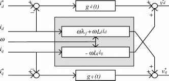 -axis current соп1гоИег FIGURE 27.44 The d- and -axis decoupling compensation. the rotor. In fact, they are dc quantities when the motor runs at a constant speed. Consequently, the following error (or lag) associated with tracking a sinusoidally time varying current reference, which is the case when current control is exercised in the stator a-b-c reference frame, can be reduced easily by using integral-type current controUers. 27.4.8 Further Reading 1. W. Leonard, Control of Electrical Drives. Springer-Verlag, 1985. 2. J. M. D. Murphy and G. G. TurnbuU, Power Electronic Control of AC Drives. Pergamon Press, 1988. 3. G. r. Slemon, Electric Machines and Drives. Addison-Wesley, 1992. 4. W. W. Novotny and T. A. Lipo, Vector Control and Dynamics of AC Drives. Oxford Science Publications, 1996. 27.5 Permanent Magnet ac Synchronous Motor Drives M. F. Rahman 27.5.1 Introduction Since the introduction of samarium-cobalt and neodymium-iron-boron magnetic materials in the 1970s and 1980s, synchronous motors with permanent-magnet excitation in the rotor have been displacing the dc motor in many high-performance apphcations. The trend is more noticeable in applications requiring high-performance motors of up to a few kUowatts. In low- to medium-power applications, the superior dynamics, smaUer size, and higher efficiency of motors with PM excitation in the rotor, compared to aU other motors, are weU known. Prior to this development, ferrite and alnico magnets were routinely used in smaU servomotors, with the magnet excitation in the outer stator. Such motors need a brush-commutator assembly to supply power to the armature, which is a problem. Nevertheless, interesting low-inertia, low-armature inductance designs are possible that are desirable for servo applications. One such design is the pancake ironless armature with the commutator-brush assembly directly located on the printed armature. These shortcomings of the commutator-brush are now avoided by locating the magnets in the rotor and by having three-phase windings in the stator that are supplied from an inverter. The arrangement just mentioned is very simUar to a conventional synchronous motor. This is particularly so when the stator windings and the rotor MMF are sinusoidally distributed. Several rotor configurations of the PM synchronous motor have been developed, of which the important ones are indicated in Figs. 27.45-27.47. q-axis 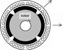 t/-axis FIGURE 27.45 Schematic of the cross section of a surface-magnet synchronous motor. FIGURE 27.48 Back emf of a trapezoidal waveform motor. -axis 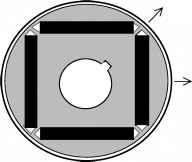 d-axis FIGURE 27.46 magnet motor. Schematic of the rotor cross section of an interior- axis 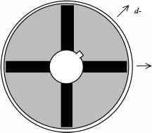 -axis FIGURE 27.47 Schematic of the rotor cross section of a circumferential-magnet motor. 27.5.2 The Surface-Magnet Synchronous Motor The surface-magnet motor comes with the rotor magnets glued onto the surface of the rotor. An additional stainless steel (i.e., nonmagnetic) cylindrical shell may be used to cover the rotor in order to keep the magnets in place against centrifugal force in high-speed applications. Since the relative permeability of the magnet material is very close to unity, the effective airgap is uniform and large. (The airgap is normally about 8 mm.) Consequently, the synchronous inductances along the rotor d- and -axes, as indicated in Fig. 27.45, are equal and small (i.e., = = LJ. The armature reaction in this type of motor is small. The three-phase winding in the stator has sinusoidal distributed windings. In another form, the motor may have trapezoidal distributed winding, and the rotor mmf is also uniformly distributed. Such a motor, often called a brushless dc motor because of its similarity to the inside-out conventional brushed PM dc motor, develops a trapezoidal back-emf waveform as indicated in Fig. 27.48, when it is driven at a constant speed. The back emf waveforms have flat tops for nearly 120° in each half-cycle followed by 60° of transition from positive to negative polarity of voltage and vice versa. These motors are very suitable for variable-speed applications such as spindle drives in machine-tool and disk drives. 27.5.2.1 Control of the Trapezoidal-Wave Motor Neglecting higher-order harmonic terms, the back emf in the motor phases may be as indicated in Fig. 27.49. Each back emf has a constant amplitude (or flat top) for 120° (electrical) followed by 60° of transition in each half cycle. The developed torque at any instant is given by (27.71) It is readily seen that the ideal current waveform in each phase needs to be a quasi-square waveform of 120° of conduction angle in each half cycle. The conduction of current in each phase winding coincides with the flat part of the back emf waveforms, which guarantees that the developed torque, i.e., (J2x=a xn hn/cr) is constant or ripple-free at all times. With such quasi-square current waveforms, a simple set of six optocouplers or Hall-effect sensors would be required to drive the six inverter switches indicated in Fig. 27.36. The output current waveforms for the three-phase inverter and the switch- 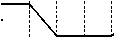 60° 120° 61 ! 12 --i-- 120° 120° 34 i 45 -h I I 12 ! 23 FIGURE 27.49 Back-emf and current waveforms and on states of transistor switches in the trapezoidal-waveform motor. ing devices that conduct during the six switching intervals per cycle are also indicated in Fig. 27.49. Since only six discrete outputs per electrical cycle are required from the rotor position sensors, the requirement of a high-resolution position sensor is dispensed with. Continuous current control for each phase of the motor, by hysteresis or PWM control, to regulate the amplitude of the motor current in each phase is normally employed. The operation of the brushless dc motor drive is described in detail in Section 27.6. Even though careful electromagnetic design is employed in order to have perfect trapezoidal back-emf waveforms as indicated in Fig. 27.49, the back-emf waveforms in a practical brushless dc motor exhibit some harmonics, as indicated in Fig. 27.48. If ripples in the back-emf waveforms are significant, then torque ripples will also exist when the motor is driven with quasi-square phase current waveforms. These ripples may become troublesome when the motor is operated at low speed, when the motor-load inertia may not filter out the torque ripples adequately. A second source of torque ripple in the PM BLDC motor is from the commutation of current in the inverter. Since the actual phase currents cannot have the abrupt rise and fall times as indicated in Fig. 27.49, torque spikes, one for each switching, may exist. Even though the PM BLDC motor does not have sinusoidal back-emf and inductance variations with rotor angle, the analysis of Section 27.4 in terms of the fundamental quantities wiU often suffice. The switching of the inverter using the six rotor-position sensors guarantees that the current waveform in each phase always remains in synchronism with the back-emf of the respective phase. Since the quasi-square phase current waveform in each phase coincides with the flat part of the back-emf waveform of the same phase, the angle у is clearly zero for such operation. Thus, considering fundamental quantities, the motor back-emf and torque characteristics can be expressed by E = KeO) volts (27.72) T = Kjl cos у = Kjl Nm (27.73) where and Kj are equal in consistent units. Note that E and / are now RMS values of the fundamental components of these quantities. 27.5.2.2 Sensorless Operation of the PM BLDC Motor In spindle and other variable-speed drive applications, where the lowest speed of operation is not less than a few hundred revs/min, it may be possible to obtain the switching signals for the inverter from the motor back emf, thus dispensing with rotor-position sensors. The method consists of integrating the back emf waveforms, which are the same as the apphed phase voltage if the other voltage drops are neglected, and comparing the integrated outputs with a fixed reference. These comparator outputs determine the switching signals for inverter. It may be noted that the amplitude of the back-emf waveforms is proportional to the operating speed, so that the frequency of the comparator outputs increases automatically with speed. In other words, the angle у and the current waveform relative to the back emf waveform in each phase remains the same regardless of the operating speed. Integrated circuits are available from several suppliers that perform this task of sensorless BLDC operation satisfactorily, covering a reasonable speed range. 27.5.3 The PM Sine-Wave Motor The PM sine-wave motor, which may also have magnets on the rotor surface or buried inside the rotor (as in the interior-magnet motor of Fig. 27.46), has sinusoidally distributed windings. The airgap flux distribution produced by the rotor magnets is also sinusoidal, arranged through magnet shaping. Consequently, the back-emf waveform of each phase is also a sinusoidal waveform, as indicated in Fig. 27.50, when the motor is driven at a constant speed. It should be noted, however, that with magnets mounted on the rotor surface, the effective airgap is large and uniform so that = = L. Because of the large equivalent airgap, these inductances are also smaU, and consequently the armature reaction is smaU. As a result, this motor essentially operates with fixed excitation, and there is hardly any scope for altering the operating power factor or the rotor mmf, once the motor and its drive voltage and current ratings have been selected. 100 v/div 5 ms/div FIGURE 27.50 Back emf waveforms of a sine-wave PM motor. Speed =1815 rev/min. The PM sine-wave interior-magnet motor, which comes with magnets buried inside the rotor as indicated in Figs. 27.46 and 27.47, has an easier magnetization path along the rotor -axis, so that > L. The small airgap implies that the inductances and may not be small, and hence may allow considerable scope for field weakening. If the sine-wave motor is supplied from an SPWM inverter, the analyses and vector diagrams of this motor are no different from those in Section 27.4 for the nonsalient-pole and salient-pole synchronous motor drives. The surface-magnet motor is more akin to the nonsalient-pole motor, since 1 = 1 = L, whereas the interior magnet motor is more akin to the salient-pole motor because of the d- and -axes inductances being unequal. Thus, the equations in Section 27.4 will apply equally well for this motor, both in the steady state and dynamically and for both voltage- and current-source supply. 27.5.3.1 Control of the PM Sine-Wave Motor The sinusoidal back-emf waveforms imply that the three-phase motor must be supplied with sinusoidal three-phase currents if a dc-motor-like (or vector-control-like) torque characteristic is desired, as was found in Section 27.4. For such operation, the phase currents must also be synchronized with the respective phase back-emf waveforms, in other words, with the rotor (i-reference frame. This implies operation with a specified у angle. Two implementations are possible. In one scheme, the stator currents are regulated in the stator reference frame and the stator current references are produced with reference to the rotor position, as indicated in Fig. 27.51. The rotor position в is continuously sensed and used to produce three sinusoidal current references of unit amplitude. The phase angle у of the references relative to the respective back-emf waveforms is usually derived from the speed controller, which defines the field-weakening regime of the drive. The operating power factor of the drive may also be addressed using the у angle control, as explained in Section 27.4.5. The amplitudes of these references are then multiplied by the error of the speed controller in order to produce the desired torque reference. In this way, both the RMS value / of the phase current and its angle у with respect to Ef can be adjusted independently (which is equivalent to independent dq-axis current control). Three PWM current controllers are indicated, but two suffice for a balanced motor. Other types of current controllers, such as hysteresis controllers, may also be used. Current Controllers Speed Controller spillover Field Weakening sin(Per+r) 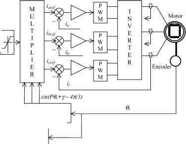 Current Reference Generator and /adjustment Speed Calculator 1 ... 66 67 68 69 70 71 72 ... 91 |
||||||||||||||||||||||||||||||||||||||||||||||||||||||||||||||||||||||||||||||||||||||||||||||||||||||||||||||||||||||||||||||||
|
© 2026 AutoElektrix.ru
Частичное копирование материалов разрешено при условии активной ссылки |