 |
 |
 |
| Главная Журналы Популярное Audi - почему их так назвали? Как появилась марка Bmw? Откуда появился Lexus? Достижения и устремления Mercedes-Benz Первые модели Chevrolet Электромобиль Nissan Leaf |
Главная » Журналы » Metal oxide semiconductor 1 ... 68 69 70 71 72 73 74 ... 91 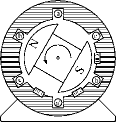 FIGURE 27.69 machine. Possible Hall-effect switch positions in a three-phase that might resuh in flux which would trip the FiE sensor at a slightly different time. If you foUow all the preceding logic about six-step switching, you wiU see that you only need the magnet poles to have a span of a bit more than 120°. Using 180° magnet poles can add considerably to the cost, as weU as having an impact on such things as cogging torque. Actual designs often add extra sense magnets to cover 180° just at the circumferential strip where the FiE switches are located, adding minimally to the magnet mass and ensuring good and accurate triggering. Fiowever, if the switches operate as shown earlier, then Table 27.3 wiU result for the FiE switches located as shown in Fig. 27.69. Figure 27.66 shows two current sensors. In the most sophisticated systems there are two current sensors, one in each of two motor phases. The current sensing is done at the winding and isolated with either an FiE sensor in a soft ferromagnetic magnetic core surrounding the conductor (commercial items are available), or by using a resistive shunt sensor and some accurate analog signal isolation/coupling through transformers or opto couplers. The isolation is necessary since the potential at points a, b, and с is either the dc bus voltage or zero, depending on which switches are on, so that any current measure such as the small voltage across a shunt is superimposed on these very large voltage changes. This is a very similar problem to that for the high-side gate drives discussed earlier. The current in the third winding is determined by the algebraic application of KCL, given the other two readings. 27,6,4,3,2 Sensing the Current in the Motor Windings Simple controUers sometimes avoid the complexities of isolated current measurement and instead measure the current in the return negative supply, for example from the bottom of the three lower switches to the bottom of the supply-smooth- TABLE 27.3 Hall-effect switch outputs for rotor positions as shown, HE switches placed as in Fig. 27.69 When the Center of the Rotor HEl HE2 HE3 Outputs North Pole is in This Sector Outputs Outputs  ing capacitor. This arrangement senses current when an upper and a lower switch is on, but not when the current is being carried in flyback diodes or by two lower switches. Although it is inexpensive, it does not provide fully accurate control. The system works because the current should be decreasing when a measure is not avaUable, heading toward zero, so switch or system faUure due to overcurrent should not occur. 27,6,4,3,3 Detail of Management of Current Sensing The controUer must select the right current to increase or decrease, dependent on rotor position. The foUowing convention is adopted. Positive current provides torque in the counterclockwise direction and therefore goes into winding a, b, or c. AU systems are capable of regeneration, which implies that negative torque can be commanded (without reversing the direction of rotation) to make the machine operate as a generator, developing retarding torque. Thus, for the preceding sequence of sector determinations, referring back to Table 27.2, the output of current sensors should be directed to the current controUer as shown in Table 27.4. The addition and negation required can be carried out with standard operational amplifier circuitry. The three required analog measures are then fed to a three-to-one analog multi- TABLE 27.4 Current sensors to use as input to the current controller for each of the six rotor position sectors Hall-Effect Switch Outputs (HEl, HE2, HE3) Monitor Current as Read by 100 110 111 Oil 001 ООО Sensor a Negative of (sensor a + sensor b) Negative of (sensor a + sensor b) Sensor b Sensor b Sensor a plexer, gated from the HE switch signals suitably processed in combinational logic. The resulting single analog output is fed to the current comparator. 27,6,4,3,4 Detail of Logic for Directing Control Signals to the Right Switches Given that dead time is introduced elsewhere in sequential logic, or with timing circuits, it is a simple matter to develop the combinational logic for directing, or steering, the switching signals to the right switches. A typical scheme for a specific controller is shown in Table 27.5. It is usual also to include some shut-down logic from dedicated protection circuits, for example sensing overcurrent, over bus voltage, undervoltage for gate drive, and over temperature both in the motor and in the controller power stage. For simplicity, this is not shown in the table. 27.6.5 Summary 27.6.5.1 What Has Been Discussed The physical principles of the operation of a PM BLDC motor have been discussed, which led to the development of the necessary parts of a power electronic controller. One specific type of current control. Hysteresis band current control, was explained in detail, and one specific type of switch logic pattern was developed. The exposition has included many of the issues that can cause difficulties for controller designers if they are not careful. TABLE 27.5 Summary of logic used to steer / up and / down signals to the correct switches and to turn on the correct lower switch, for the scheme discussed in section 27.6.2
27.6.5.2 What Has Not Been Discussed Many PM BLDC motors have more than one pair of poles. The foregoing arguments can all be extended to higher pole-count machines by taking any mention of degrees to be electrical degrees rather than mechanical degrees. The controller discussed in detail only manages one direction of rotation. It is an excellent exercise, and straightforward, but not trivial, to repeat the preceding steps, preparing the tables for clockwise rotation of the simple machine discussed earher. Then, following the discussion in the first part of Section 27.6.3, Current/Torque Control about H-bridge switching, prepare the logic tables again for full bidirectional control, using the / up and / down logic signals exactly as before, but applying them to both legs determined by the rotor position. Only one form of current sensing was discussed in detail. There are many simpler schemes in use that do not have quite the flexibility and accuracy of the foregoing, but that can suit certain applications. Similarly, there are other forms of current control, such as the constant frequency linear method briefly discussed. Shaft-position sensors take many forms. Adherence to the HE sensor was for simplicity, and to reinforce the magnetic-field aspects of the machine operation. 27.6.6 Further Reading Apart from power electronics texts, which usually cover this area very sketchily, there are three small books that are specifically about machines, but have more detail on the range of controllers used. 1. Timothy J. E. MiUer, Brushless Permanent-Magnet and Reluctance Motor Drives. Oxford University press, 1989. For square-wave brushless dc motors. 2. T. Kenjo and S. Nagamori, Permanent-Magnet and Brushless DC Motors. Oxford University Press, 1985. For smaU machines used particularly in consumer electronics. 3. Duane C. Hanselman, Brushless Permanent Magnet Motor Design. McGraw-Hill, 1994. For the possible range of controllers in the last chapter. 4. Application notes from the various integrated circuit companies, particularly those that specialize in motor control. 27.7 Servo Drives M. F. Rahman 27.7.1 Introduction Servo drives are motor drives that operate with high dynamic response. Historically, servo drives have implied motion-control systems in which sophisticated motor design, drive, and control techniques have been employed to obtain very much shorter positioning times than is possible with conventional drive systems. Examples are in machine tool drives. robotic actuators, computer disk drives, and so on. The power range for these drives has typicaUy been in the range of a few kilowatts or less. This range has steadily increased in recent years as a result of advances in magnetic materials, machine design, power and signal electronic devices, and sensors. Apart from the fast positioning times, high dynamic response also means that the drive operates with the foUowing: 1. Very smooth torque up to a very low speed 2. Very high reliability and little maintenance 3. Immunity from load disturbances The last of the foregoing items is brought about by robust and inteUigent control algorithms; the first two items are brought about by innovative and often costly motor and controUer designs. As a resuh of these, the cost of a servo motor drive is usually much higher than equivalent power rated industrial drives. The distinctions just mentioned may be easily recognized by noting, for example, that the drives that bring material in a miU may not require high performance, but the drives that take part in shaping, miUing, or reducing the material should have high dynamic response in order to increase throughput and meet the accuracy requirements of the final product. 27.7.2 Servo-Drive Performance Criteria The performance of a servo drive can be expressed in terms of a number or factors such as servo bandwidth, accuracy, percentage regulation, and stiffness. While servo bandwidth indicates the ability of the drive to track a moving or cyclic reference, the percentage regulation and stiffness stipulates the drives static holding performance for speed or position, in the face of disturbances from the load and in the supply conditions. The servo bandwidth, given as a frequency in hertz, is often found from the system frequency response plot, such as the Bode diagram. The percentage regulation of a speed-controUed system often refers to the percentage change in speed from no load to fuU load. In a type-zero system this figure wiU have a finite value. Many systems are type zero, albeit with a high gain so that the regulation is acceptably low. For such systems, the regulation is often necessary for operational reasons. In some apphcations, zero percentage error is required, which caUs for type 1 or integral type control system. The servo stiffness is simUar to the percentage error mentioned earher, but it applies mainly for the position servo. It specifies the deflection of the load from its reference position when fuU load torque is applied. Its is usually the slope of the deflection versus the applied load torque in rad/Nm around the reference position. 27.7.3 Servo Motors, Shaft Sensors, and Coupling Servo drives use motors that aUow the desired goals of high dynamic response to be achieved. The foUowing are the important parameters/attributes of a servo motor: 1. High torque-to-inertia ratio 2. High torque-to-volume ratio 3. Low inductance of the motor windings 4. Low cogging torque at low speed 5. Efficient heat dissipation 6. Low coefficient of shaft compliance 7. Direct coupled, high-resolution, shaft-mounted sensors for position and speed High torque-to-inertia ratio aUows fast acceleration or deceleration of the drive when motion references are changed. This is often achieved through innovative low-inertia rotor design and low inductance in the stator winding. One example of a dc servo motor is the pancake printed armature dc motor with no iron in the rotor, as indicated in Fig. 27.70. The rotor is sandwiched between axially mounted stator poles. The commutator is also on the printed armature. Another example is the disk rotor stepping motor, also without iron in the rotor, as indicated in Fig. 27.71. PM ac synchronous motors with modern high-energy-density magnets in the rotor, as described in Section 27.6, are also examples where the motor designer strives to minimize the rotor inertia. Modern permanent magnets aUow the required airgap flux to be developed with a much-reduced volume of the magnets, consequently reducing the diameter of = electrical time constant = - FIGURE 27.71 A disk rotor stepping motor with ironless rotor for low inertia and inductance. Courtesy: Escap Motors. the rotor. It is well known that the moment of inertia of a motor increases as the fourth power of its outer radius! Another benefit of the modern permanent magnet material is that the motor volume is also reduced. Servo motors often have to be located in a very confined space, and this reduction is volume is an important attribute. The ironless designs mentioned earher bring other benefits in the form of reduced inductance and cogging torque. Brushed pancake ironless motors are available with armature inductance as low as 100 pH. From Section 27.2.2, the mechanical and electrical time constants of a brushed dc motor are given by = mechanical time constant = KeKt It is well known that for the highest load acceleration, the load inertia referred to the motor should be equal to the rotor inertia. Thus, in a matched system, the total inertia the motor accelerates is twice its own inertia. In other words, the motor inertia should also be minimized. For a good servo motor, the ratio between the mechanical and the electrical time constants is often of the order of five or more. This allows the speed and the current-control loops to be decoupled and noninteracting. The electrical time constant of a motor determines how quickly the motor current may be changed and hence how quickly torque can be developed. As also mentioned in Section 27.2, drives with a reasonable dynamic performance should have an inner torque loop. This torque loop is built around current loops, for the armature for the brushed dc motor, or for the d- and -axis currents for the induction and synchronous motor drives. Having a low inductance in the winding allows these currents to be followed dynamically changing current or torque references with higher accuracy and bandwidth. The cogging torque, if appreciable, causes the rotor to have preferential positions. As a result, the position accuracy of the motor may suffer. Another problem is the ripple in speed as the motor is operated at low speed. At high speed, these ripples due to cogging torque may be filtered out by the motor inertia; however, the extra loss due to cogging remains. The ironless or toothless rotor obviously produce very small cogging torque because of the absence of preferential paths for the airgap flux to establish through the rotor iron of the brushed dc motor. The surface magnet synchronous motor also has this feature. The interior magnet motor normally has skewed stator slots to avoid production of cogging torque. Servo motors often operate with frequent start-and-stop duty, with fastest allowable acceleration and deceleration during which the motor current is allowed to reach about 2 to 3 times the continuously rated current. The increased fR loss in such duty must be dissipated. This calls for adequate coohng measures to be incorporated in the motor housing. With such operation, it is sometimes possible to excite mechanical resonance due to shaft comphance. This is avoided through proper arrangement of the shaft position/speed sensor and the coupling between the motor and the sensor. A belt-driven speed sensor may be acceptable for an industrial drive; however; for servo applications, a rigid, direct-coupled sensor mounted as close as possible to the motor armature is preferable. Additionally, the speed sensor is also required to have negligible noise. Speed signal from analog tachogenera-tors, which were used for speed sensing until recently, invariably needed to be filtered to remove the cyclic ripple/noise that existed. Such fihering often hmits the maximum speed-control bandwidth of a drive. 27.7.4 The Inner Current/Torque Loop The inner current loop(s) in a servo motor drive play a more important role than just hmiting the current in case of overload. These loops operate continuously to regulate the motor-developed torque so as to meet the load demand, and for meeting the speed trajectory specified by the motion controller. Motor drives of high dynamic response currently employ PWM current sources. These sources use MOSFET or IGBT switching devices that aUow the modulator to be operated with a switching frequency between 10 and 25 kFiz. At these frequencies, the inherent switching delay, which is equivalent to half of the PWM switching period, is made rather smaU for the bandwidth of the torque control loop. The bandwidth of the current control loops closely represents the bandwidth of torque control. This because the motor-developed torque generally proportional to these currents. Servo drives up to a few kilowatts presently have torque/current control-loop bandwidths in excess of 1 kFiz. For higher power, fast-response drives, such as those used in the metal-processing industries, thyristor converters have been used for many years. The switching frequencies of these converters are rather low, being some multiple of the mains frequency, according to the converter chosen. Fortunately, the larger mechanical time constant of the larger power motor and the nature of the applications have aUowed the 300-Fiz (360-Fiz in the United States) switch frequency of the three-phase thyristor bridge converter to be used satisfactorily in many apphcations requiring high dynamic response. The growing avaUabUity of faster and higher power IGBT devices is continually enhancing the dynamic performance of larger drives. Fast-response, inner torque-control loops have in recent years been extended to ac induction and synchronous motors. These motors were hitherto considered only for industrial drives. The vector methods described in Sections 27.3 and 27.4, which employ inner quadrature axis current controUers in the synchronous (for the induction motor) or the rotor (for the synchronous motor) reference frame, have transformed the prospects of ac motor drives in servo apphcations. Because of the fast dynamic response requirement of servo drives, the servo motor is nearly always driven with the maximum torque per ampere (MTPA) characteristic. Field weakening is normally not used. In other words, field control either directly for a brushed dc motor or a synchronous motor or indirectly through armature reaction (i.e., through current control) for induction or PM ac synchronous motors is not used for field weakening. It is nevertheless used for regulating the field at the desired level. Field weakening is mainly used for drives where operation at higher than base speed with constant-power characteristic is desirable. 27.7.5 Sensors for Servo Drives Servo drives require high-bandwidth current sensors for the inner torque loop and high-accuracy, noise-free speed and position sensors for the outer loops. The current sensor is often a FiaU device with an amplifier, which can have band-widths as high as 100 kFiz. The inner current loop both limits and continuously regulates the motor current in aU operating modes of the drive, including acceleration and deceleration. About 2-3 times the continuous rated current of the motor is tolerated during acceleration and deceleration. This entaUs limiting the speed controUer output to the level corresponding to the current sensor output for the limiting values of motor currents. The current-sensor output has to be filtered to adequately remove the switching frequency noise. Otherwise, certain switching devices in converter may be overloaded. This task is more important for the thyristor converters for dc drives for which the switching frequency is rather low. This filtering of the current sensor output limits the bandwidth of the current-control system, i.e., the inner torque-control loop. Performance of servo-motor drives depends critically on the noise and accuracy of the speed and position sensors. Synchro-resolvers with 12-bit or higher digital accuracy were used in many servo-drive systems untU recently. The advent of cheaper incremental and absolute optical encoders has altered this situation completely. These digital sensors are actually position sensors. The speed information is derived from positions measured by discrete differentiation. Such differentiation is not feasible with analog position sensors, because of the noise. Analog tachogenerators are also avoided for speed servo systems. This is because of the tachogenerator ripples inherent in the sensor. Modern discrete position sensors provide for virtually noise-free speed and position sensing. This aUows very fast dynamic response to be achieved if the switching frequency of the converter aUows it. 27.7.6 Servo Control-Loop Design Issues 27.7.6.1 Typical Controllers 27,7,6,1,1 Proportional Controller A proportional controller provides for a straight gain to amphfy the error signal. It has no discriminatory properties. With the input and feed resistance values indicated in Fig. 27.72, the total gain of the controller is -h 1. For this controUer, (27.79) 27,7,6,1,2 Transient Velocity Feedback Controller It is weU known that a foUowing error wiU exist in the preceding system when a moving or ramp reference is tracked. If a rate feedback. 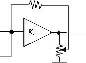 FIGURE 27.72 Proportional controller. eo=Kie R С -ЛЛЛ/-  FIGURE 27.74 Integral-type controller. such as the speed feedback in a position-control system, is used to damp the system, this error is further increased. To overcome this following error due to velocity feedback, transient velocity feedback can be used as indicated in Fig. 27.73. The speed (velocity) signal is passed through an RC circuit at the input of the amplifier circuit. An input current occurs only when the speed signal changes. In the steady state, the capacitor is fully charged, so that no following error in the steady state due to the velocity feedback can exist. In the steady state when the velocities are equal, the output may lag or lead depending on the relative values of R and R2. It can be shown that in the absence of frictional load torque, as is often the case in servo applications, no following error is introduced if R = R2- 27,7,6,1,3 Integral Controller In the transient-velocity and error-rate feedback schemes, a following error will exist if viscous friction and load torque are present. If such loads are present, the system gain has to infinity to have zero error. Very large gains will make any physical systems unstable, unless bandwidth limitations exist. One way to employ infinite gain in the steady state is to use an integrator. This amplifies the steady-state error until it is ehminated. Normally, a proportional plus integral (PI) action is used. A derivative term is normally not used in the control system of a drive system, since the drive feedback signals are very noisy. Instead, derivative signals are obtained through sensors such as tachogenerators. The structure of a PI controller is indicated in Fig. 27.74. It can be shown that there will be no steady-state error even in the presence of frictional or other load torque. Many types of more complex controllers are available, such as the variable-structure controller. Drives with fuzzy controllers have also been in the marketplace for some years. The controller circuits just described are usually implemented in analog circuits using operational amplifiers. Digital implementations are also being gradually introduced using embedded microcontrollers and digital signal processors. 27.7.6.2 Simplified Drive Representarions and Control Consider the block diagram of Fig. 27.75 in which individual elements (blocks) are represented in terms of their transfer functions in terms of the Laplace operators. Here, G(5), Gc(s), Gi(s), Я^(5), and Hp(s) represent the transfer functions of the power converter plus the motor, the controller, the load, the sensor (of speed in this example), and the filter following the sensor, respectively. The reference input for speed and the feedback signal are connected to a summing junction of an operational amplifier through resistors R and Rp respectively. The preceding system can be simphfied to that shown in Fig. 27.76, and further to that in Fig. 27.77. In general, if the individual control blocks are approximated as first-order systems and are mutually decoupled, meaning that each block operates in a frequency band that is far outside 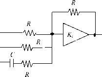 -ЛЛЛл- \- Zc(s) Controller Ga(s) (power converter + motor) (Filter) -TUs) Gl(s) (Load) (Sensor) Ei(s)
FIGURE 27.76 Simplified representation of Fig. 27.75. Ei(s) Rf/Ri 0- Gc(s) Ga(s) Gl(s) Ht(s) H/s) FIGURE 27.77 Further simplified representation of Fig. 27.75. the frequency bands of all other blocks, then the foregoing systems can be represented by a transfer function of the form G,(s) = К (l+5Ti)(l+5T2)(l+5T3)(l+5T4). (27.80) When T3 and T4 are much smaUer time constants than and t2, the preceding may be approximated by Gi(5) = К (1 + 5Ti)(l + sTXl + sT,) (27.81) where = T3 + T4 H----, etc. A dc-motor speed-control system with current and speed sensors faUs in this category. For such a system there exist two dominant time constants (poles). For such a system, a proportional plus integral controUer is of the form (1 + 5Ti)(l + 5T,) 5T,(1 -h 5Tpi)(l + -2) (27.82) One optimization criterion (Kesslers) stipulates that T, T2 t2, and = 2KT. With this stipulation, the transfer function of the complete system is given by G(5) = Gi(5)G,(5) = V(s) Vi(s) 1-hG l-h25T,-h252T, (27.83) (27.84) Note that two filter time constants Тр and are included in G(s) for the sake of its reahzabUity. These can be relegated to frequencies far higher than the range of interest and can be 0.043 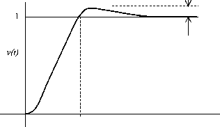 4.7L t FIGURE 27.78 Response of the optimized system of Fig. 27.75. ignored for further analysis of the system. For an unit step input of the output v is given by v{t) = 1 - Vle- (2 i) - ( ) A typical output is sketched in Fig. 27.78. If the transfer function Gi(s) has one dominant time constant Ti(s), as for the field current control of a dc motor, a suitable controller is the form (I+5T1) 5T,(1 + sTp) In some cases, the transfer function Gi(s) is of the form К (27.86) G,(s) = 5Ti(l+5T2)(l+5T,) (27.87) where is the sum of a number of short time constants, associated with sensors, switching frequency, and so on. The current controUer of the dc motor with back emf has such a characteristic. A suitable PI controUer for this system is G,(5) = (1 + 5Ti)(l + 5T2) (27.88) 5T1 -h 5Tpi)(l + 2) For this system, Kesslers optimization criterion stipulates that = T2 = t2, and T, = The transfer function of the complete system is then V(s) 1 -h 45T, Vi(s) 1 -h 45T, -h 852 Tj -h 85З (27.89) The peak overshoot of this system to a unit step unit is usually unacceptable, as indicated by the response of Fig. 27.80. This
G/s) G,(s) FIGURE 27.79 Block diagram representation of a typical current controller. Without input filter 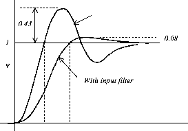 3.1Ts 7.6Ts Time, msec FIGURE 27.80 Optimized response of the system of Fig. 27.79. overshoot is usually reduced by inserting a first-order filter in the reference circuit. The filter network and the responses are given in Fig. 27.79. 27.7.7 Further Reading 1. George W. Younkin, Industrial Servo Control Systems: Fundamentals and Applications. Marcel Dekker, 1996. 2. B. C. Kuo and J. Tal, Incremental Motion Control 1: DC Motors and Systems. SRL Pubhshing, 1978. 3. D. Shetty and R. Kolk, Mechatronics Systems Design. PWS Publishing, 1997. 4. A. Fransua and R. Magureanu, Electric Machines and Drive Systems. Techical Press, Oxford, 1984. 27.8 Stepper Motor Drives M. F. Rahman 27.8.1 Introduction A stepper motor is a positioning device that increments its shaft position in direct proportion to the number of current pulses supplied to its windings. A digital positioning system without any position or speed feedback is thus easily implemented at a much lower cost than with other types of motors, simply by delivering a counted number of switching signals to the motor. Typically, a 200-steps-per-revolution stepper motor with 5% stepping accuracy will be equivalent to a dc motor with a 12-bit (or 4000 counts/rev) encoder plus the closed-loop speed and position controllers for obtaining similar positioning resolution. This advantage, however, is obtained at a cost of increased complexity of the drive circuits. A disadvantage of the motor is perhaps its inability to reach an absolute position, since the final position reached is only relative to its arbitrary initial position. Nevertheless, the true digital nature of this motor makes it a very suitable candidate for digital positioning systems in many manufacturing, automation, and indexing systems. The working principle of stepper motors is based on the tendency of the rotor to ahgn with the position where the stator flux becomes maximum (i.e., seeking of the minimum-reluctance position, also called the detent position). The rotor and the stator are both toothed structures, and the stator normally has more than two windings to step the rotor in the desired direction when they are energized in certain combinations with current. Some motors additionally have permanent magnets embedded in the rotor that accentuate an already existing, zero-excitation detent torque. These motors hold their positions even when the stator excitations are removed completely, a feature desirable for some applications. In addition to the point-to-point stepping action, these motors can also be operated at high slewing speed, simply by increasing the pulsing rate of phase currents. Since the motor is inherently a synchronous actuator, the pulsing rate has to be increased and decreased properly, so that the rotor may follow it. At the end of a complete run, the motor always stops at the desired incremental position or angle without any accumulated error. The only error that may be encountered is mainly due to the machining accuracy of the teeth in the stator and rotor. This error is of the order of about 5% of one step position/angle and it is nonaccumulative. 27.8.2 Motor Types and Characteristics 27.8.2.1 Single-Stack Variable-Reluctance Stepper Motor Single-stack motors are normally of the variable-reluctance type with no excitation in the rotor. The cross section of a three-phase motor with two stator poles/phase and four rotor poles are indicated in Fig. 27.81. The motor can be stepped clock or anticlockwise by energizing the phase winding in the ABCA or ACBA sequence, respectively. The step angle, i.e., the angle moved by rotor for each change in excitation sequence, of the motor is given by 360° (27.90) where N is the number of phases in the stator and p is the number of poles in the stator. Single-stack motors typically has larger step angles than other types because of hmitations of 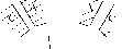 X../ FIGURE 27.81 Cross section of a single-stack variable-reluctance stepper motor. space for the windings. The step angle of these motor tend to be larger than the multistack and hybrid stepper motors. For each excited winding, the motor develops a torque-angle (Т-в) characteristic as indicated in Fig. 27.82. Note there are two equilibrium positions of the rotor, namely, X and 7, where the motor develops zero torque. The position X is referred to as the stable detent position, around which the rotor develops a restoring torque when displaced. The restoring torque increases as the rotor is moved from its detent position, becoming a maximum T on either side of this position. The slope of the Т-в characteristic around this detent position and the maximum torque, both of which depend on the level of excitation, indicate how far the rotor wiU be displaced under load torque. This means that the level of excitation also affects the position holding accuracy of the motor. The motor may also be excited in the sequence: AB-BC-CA or AB-CA-BC for forward and reverse stepping, respectively. The two phases-on scheme develops more torque around the detent positions at the expense of twice the resistive losses. Yet another excitation scheme is AB-B-BC-C-CA-A-AB for forward stepping and AB-A-AC-C-BC-B-AB for reverse stepping. In this scheme, the step size is halved as opposed to the full-step size of the previous sequences. Two different levels of torque is produced for alternate detent positions. Fiowever, the reduced step size and the more damped nature of each step may outweigh this disadvantage. 27.8.2.2 Multistack Variable-Reluctance Stepper Motor In a multistack variable-reluctance motor, the stator windings are stacked along the shaft. Each stack section now has the same number of poles in the stator and the rotor. Normally each stator stack is staggered with respect to its neighbor by one Nth of a pole pitch, where N is the number of stator/ rotor phases or sections. The cutout view of Fig. 27.83 shows some internal details of a six-phase multistack motor, in which each stack has a phase winding between two rings, each with 32 stator and rotor poles. The step size of this motor is 360° 360° 6 X 32 = 1.875° (27.91) The excitation sequence of this motor is similar to the ones mentioned in Section 27.8.2.1, except that more excitation sequences are available. When a stator winding is energized, the rotor poles of that section tend to align with those defined by the stator excitation. The stator and rotor teeth in the other sections are not aligned. By changing the combination of excited phases to the next in sequence, the rotor is made to move by one step angle. 27.8.2.3 Hybrid Stepper Motor A hybrid stepper motor has an axially oriented permanent magnet sandwiched between two sections of the stator and rotor, as indicated in Fig. 27.84. The magnet flux distributes radially through the two stator and rotor sections, both of which are toothed, and axially through the back iron of the stator and the shaft. The stator has two phase windings, each of which creates alternate polarities of magnetic poles in both 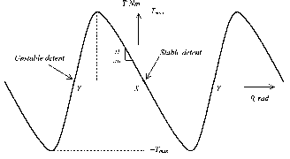 Stator and Rotor sections - Stator winding  Stator winding FIGURE 27.84 Axial section of the hybrid motor. sections of the stator. Stator windings are excited with bipolar currents, as opposed to the unipolar currents in the variable-reluctance motors of the two preceding sections. The magnetic flux produced by the stator windings is circumferential in each stator and rotor section, but also crosses the airgap radially. It does not, however, pass through the rotor magnet. The two rotor sections are offset by half its tooth pitch. The rotor magnet causes to the stator and rotor teeth to settle at the minimum reluctance position with a modest amount of detent torque to keep the rotor in position when the stator windings are not energized. The rotor magnet flux distributes outward through stator poles 3 and 7 in section X and inward through poles 1 and 5 in section 7, as shown in Fig. 27.85a and 27.85b. When stator windings A and В (indicated as dark and faint shaded, respectively) are energized with positive and negative currents, respectively, the resulting stator flux also distributes through these same poles, so that the rotor then develops a much higher detent torque (Т-в) characteristic. The motor can be stepped forward or backward by energizing windings in sequence AB-AB-AB-AB or AB-AB-AB-AB, respectively, where the overbar indicates the polarity of currents in phases A and B. The stepping angle of a hybrid stepper motor is given by 90° (27.92) where p is the number of rotor poles. IJ.S.IA Permanent-Magnet Stepper Motor Permanent-magnet stepper motors have alternate polarities of permanent magnets on the rotor surface while the rotor iron, if it is used, has no teeth. In one type of construction, the rotor has no iron, and the stator consists of two windings that set up alternate poles when energized, just as in the case of the hybrid motor. The rotor consists of permanent magnets, alternately polarized, attached to the surface of a nonmagnetic disk, as shown in Fig. 27.86. The stator and rotor fluxes cross the airgap, one on either side of the disk, axially. 27.8.3 Mechanism of Torque Production 27.8.3.1 Variable-Reluctance Motor If it is assumed that the current in the excited winding remains constant, the production of static torque of a variable reluctance motor around a detent position is given by (27.93) Phase A  Phase A   Phase В (a) (b) FIGURE 27.85 Cross section of the hybrid motor, (a) Section X; (b) section Y. Phase В 1 ... 68 69 70 71 72 73 74 ... 91 |
|||||||||||||||||||||||||||||||||||||||||||||||||||||||||||||||||||||||||||||
|
© 2026 AutoElektrix.ru
Частичное копирование материалов разрешено при условии активной ссылки |