 |
 |
 |
| Главная Журналы Популярное Audi - почему их так назвали? Как появилась марка Bmw? Откуда появился Lexus? Достижения и устремления Mercedes-Benz Первые модели Chevrolet Электромобиль Nissan Leaf |
Главная » Журналы » Metal oxide semiconductor 1 ... 69 70 71 72 73 74 75 ... 91 FIGURE 27.86 Rotor of a PM stepper motor. Courtesy: Escap Motors. This torque expression may also be expressed as in (27.94) when it is further assumed that the inductance of the excited winding at any given position remains constant for all currents (27.94) The developed torque is due to the variation of inductance (or reluctance) with position. Note that the direction of current has no bearing on the developed torque. When the stator and rotor poles are perfectly ahgned, as indicated in Fig. 27.87a, the inductance L changes little with a smaU change in в. The developed torque is thus very smaU around this position, corresponding to the position X in Fig. 27.82. When the stator and rotor teeth are unaligned, as in Fig. 27.87b, L changes more significantly with в, and the restoring torque becomes much larger. As в increases, dL/dO goes through a maximum, producing Tix- It should be noted that around a stable detent, L reduces as в increases, so that the slope of the Т-в characteristic is negative at the origin. Beyond the position where T is developed, L increases as a result of the next set of rotor teeth coming under the stator teeth. This explains the drop in T and the positive slope of the Т-в characteristic in the region between where T is developed and Y in Fig. 27.82. If stepper motors are operated in magnetically linear region where L remains constant with current for a given angular position, the developed torque per unit volume is smaU. Because of this, steppers motors are normally driven far into saturation. Equation (27.94) then does not represent the torque characteristic adequately. For a saturated stepper motor, the calculation of the Т-в characteristic for any given current involves complex computation of stored energy, or coenergy, for each position of the rotor. This requires the magnetization characteristics of the motor for different levels of stator currents and rotor positions to be known. Reference [1] at the end of this section may be consulted for further reading on this. 27.8.3.2 Hybrid and PM Motors In hybrid stepper motors, most of the developed torque is contributed by the variable-reluctance principle explained earlier. The rest is developed by the rotor magnet in striving to find the minimum-reluctance position. It should be noted that the alternate polarities of the magnetic poles created by each winding may be reversed by the direction of its current. Consequently, the polarity of the winding currents also determine the direction in which the developed torque increases positively around a detent position. 27.8.4 Single- and Multistep Responses When the rotor is at a detent position and phase currents are changed to a new value, the detent position is moved and the rotor proceeds towards it and settles down at the new detent position. The movement of the rotor is influenced by shape of the Т-в characteristic and the load friction. The rotor stepping is normally quite underdamped. The final positioning error is also determined largely by the load torque. For instance, if the Т-в characteristic is assumed to be a sinusoidal function of в, the error in stepping is given by Eq. (27.95), where T is the peak of the Т-в characteristic and T is the load friction torque (27.95) Fiowever, this error does not accumulate as further stepping is performed. If the phase currents are switched in succession, the rotor makes multiple steps. Typical single and multistep responses are as indicated in Fig. 27.88. 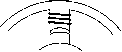 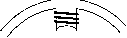 The maximum rate at which the rotor can be moved depends on several factors. The rise and fall times of the winding currents, which are largely determined by the electrical parameters of the windings and the type of drive circuits used, and the combined inertia and friction parameters of the motor and load are important factors. The discrete signals to step the motor in the forward or reverse direction are translated into current-switching signals for the drive circuits. This translator is a simple logical operation that is embedded in most of the integrated circuits available for driving stepper motors. In many applications, the stepper motor is operated at far higher speeds than it can start/stop from. The performance of a stepper motor at high speed is normally given in terms of its pull-out torque-speed (Т-ш) characteristic. This characteristic indicates the maximum average torque the motor may develop while stepping continuously at a given rate. This torque is also largely determined by parameters of the motor and its drive circuits. Figure 27.89 indicates the typical shape of the pull-out T-co characteristic of a stepper motor drive. At low speed, the pull-out torque is roughly equal to the average value of the positive half-cycle of the Т-в waveforms of Fig. 27.82. At high speed, the finite but fixed rise and fall times of currents and the back emf of the winding reduces the extent to which the windings are energized during each Pull-out torque, Nm 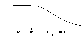 Stepping rate in steps/sec FIGURE 27.89 Typical pull-out torque characteristic of a stepper motor. switching period. Consequently, the pull-out torque of the motors falls as the stepping rate (speed) increases. For operation at high speed, the stepping rate is gradually increased and decreased from one speed to another. Without careful acceleration and deceleration to and from a high speed, the motor will not be able to follow the stepping commands and will lose its synchronism with the stepping pulses or winding excitations. The acceleration and deceleration rates of a stepper motor are also determined largely by the pull-out torque characteristic. Stepper motors are known to suffer from mechanically induced resonance and consequent misstepping when its switching rate falls within certain bands, which are largely determined by the way the developed torque varies with time as the motor steps. Careful selection of stepping rate is normally employed to overcome the problem. Some shaft-mounted external damping measures may also be used when the stepping rate needs to be continuously varied, such as in the case of machine-tool profile following. 27.8.5 Drive Circuits Two types of drive circuits are in general use for stepper motors. The unipolar drive is suitable for variable-reluctance stepper motors, for which the developed torque is determined by the level of current, not its polarity. For hybrid and permanent-magnet motors, the direction of current is also important, so that bipolar drive circuits are more suitable. 27.8.5.1 Unipolar Drive Circuits In its simplest form, the unipolar drive circuits, one for each winding, are as indicated in Fig. 27.90. The transistor (MOSFET) is turned on to energize the winding, with a current that is limited either by the winding resistance or by hysteresis or PWM current controllers. The free-wheeling diode allows the winding current a circulating path when the transistor is turned off. Winding A Gate Drive Circuit 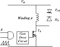 Ш Gate Drive Circuit b Tai Winding A Winding A mr\ M7\D4 Winding В rrm GND GND FIGURE 27.91 Bipolar drive circuit (gate-drive circuits omitted). The drive circuit of Fig. 27.90a is a basic one. A better drive circuit is shown in Fig. 27.90b, which includes a zener diode in the freewheehng path. A pulse-width modulator is also included in the gate driving circuit. The pulse-width modulator aUows a higher dc supply voltage (typically 5-10 times the voltage for the resistance-limited drive) to be used, thereby reducing the rise time of current at switch-on by 5 to 10 times. The zener diode aUows a fast faU time for the current when the transistor is turned off by dissipating the trapped energy of the winding at switch-off faster. Yet another scheme is shown in Fig. 27.90c, which allows the trapped energy of the winding at switch-off to be returned to the dc source when the transistor is turned off, rather than being dissipated in the winding or the freewheehng circuits. This circuit is by far the most efficient, and at the same time gives the fastest possible rise and fall times for the winding currents. 27.8.5.2 Bipolar Drive Circuits The bipolar drive aUows the motor windings to driven with bidirectional currents. The four-transistor bridge drive circuit of Fig. 27.91; one for each winding, is the most popular. The circuit can cater to the required rise and faU times of the winding by properly selecting the dc supply voltage V, the pulse-width modulator, and the current controller gains. Some hybrid and PM motors come with four windings, two for each phase. These may be connected in series or parallel, depending on the torque characteristics desired. In any case, only two drive circuits of the type indicated in Fig. 27.91 are required. 27.8.5.3 Drive Circuits for Bifilar Wound Motors Fiybrid stepping motors may also come with bifilar windings, which allow the simpler unipolar drive circuits to be used. These motors have two tightly coupled windings for each phase. Figure 27.92 illustrates two bifilar windings on stator pole and their unipolar drives. The two windings on each pole have opposite sense, so that the magnetic polarity is reversed by simply switching the other winding. Since only unidirectional current is involved, the unipolar drive circuits of Fig. 27.90a or 27.90b may be used at a considerable savings in terms of the drive circuits. This benefit, is however, derived at the cost of extra winding space, and hence larger volume, for the same torque. 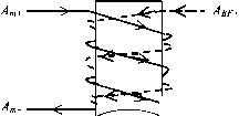 Main winding Bifdar winding Main Winding (phase A) 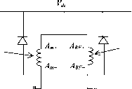 Bifilar Winding (phase A)
(a) (b) FIGURE 27.92 Drive circuits for one phase of a bifilar-wound motor, (a) Bifilar pole windings; (b) drive circuits. T, Nm T, Nm T,Nm Phase A Phase В Phase С FIGURE 27.93 Т-в characteristics of a three-phase variable-reluctance motor. 27.8.6 Microstepping The drive sequences mentioned in Section 27.8.2 normally switch rated current through the motor windings. These produce regular step angles. The half-stepping operation also uses rated motor currents. Halving of the step angle is arranged mainly through the selection of the windings switched. In microstepping, the regular step angle of the motor is subdivided further by a factor, typically from 10 to 100, by energizing the winding partially, with combinations of currents ranging from zero to full rated value in more than one winding simultaneously. This does not lead to any sacrifice of the developed torque, since the phase currents are so selected that the peak of total torque contributed by two partially energized windings is not lower than the peak detent torque Tjax obtained in regular stepping. The idea behind microstepping is readily understood when it is considered that by increasing the current in phase A of a two-phase hybrid in 10 equal steps to full value and decreasing the current in phase Б in a similar manner, the motor step size may be divided by a factor of 10. If closed-loop current controllers are added to the two drive circuits of Fig. 27.91 and distinct current references are obtained from a reference generator, a complete microstepping drive is realized. In microstepping, the two current references must have values such that the motor does the following: 1. Develops the same T for every combination of winding currents 2. Develops the same torque slope, i.e., dT/dO at every microstepping detent position 3. Dissipates no more than the rated power loss (IR) for every combination of winding currents The preceding conditions are necessary if the motor is to retain its static accuracy, maximum torque, and power dissipation characteristics. The static torque characteristics (Fig. 27.92) of stepper motors are close to but not exactly sinusoidal functions of angle 9. The required current references for all windings of a stepper motor, including the variable reluctance motor of three or more phases, can easily be calculated from the data of the Т-в characteristics of the motor for each phase for various currents and rotor positions. A typical set of Т-в data for a three-phase variable-reluctance motor is shown in Fig. 27.93. The application of the three conditions mentioned earlier leads to an unique set of current references for each phase of the motor for each microstep. Figure 27.94 shows the current references for this motor for microstepping. In multistepping operation, these microstepping current references have to be issued to the current controllers for each phase, at a rate determined by the commanded stepping rate. Care has to be taken in designing the phase current controllers so that actual winding currents match the current references in both single and multistepping operation up to the maximum stepping rate desired. Since the current references are time varying, high-bandwidth current controllers are normally required to cover the desired speed range. 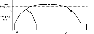 Time, t FIGURE 27.95 Typical acceleration/deceleration profiles. 27.8.7 Open-Loop Acceleration-Deceleration Profiles As mentioned in Section 27.8.4, many applications require the stepper motors to be driven far above the stepping rates to and from which the motor can start and stop abruptly without losing or gaining any step. This caUs for carefully designed acceleration/deceleration profiles that the stepping pulse rate must not exceed. The number of steps the motor is to be stepped and its direction are normally under the control of the motion controller. Once this reference is known, a digital timer/coun-ter circuit can be used in the controller to progressively adjust the time between the stepping pulses such that a prescribed acceleration/deceleration profile, as indicated in Fig. 27.95, is followed. The timer/counter and the pulsing sequence controller (the translator) need to be managed in real time to execute the motion-control task at hand. The fastest acceleration-deceleration profile a stepper motor is capable of is largely determined by its puU-out (T-co) characteristic, which in turn is determined by the motor winding parameters and the drive circuit. An optimized stepping profile to and from the top speed may have a number of segments, as indicated in Fig. 27.95. These profiles are easily computed from the pull-out (Т-ш) characteristic by integrating the dynamic torque balance equation of the drive. For a large positioning angle, the entire profile, including some constant-speed running at the top speed, may be used. For short positioning angles, only part of the profile may be traversed. In general, a single-segment acceleration-deceleration profile is used in commercial stepper motor controllers, so as to avoid a great deal of realtime number crunching by the profile controUer. The overaU stepper motor controller thus consists of the blocks depicted in Fig. 27.96.
f Stepper \ motor 27.7.8 Further Reading 1. H. B. Ertan, A. Hughes, and P. J. Lawrenson, Efficient numerical method for predicting the torque-displacement curve of saturated VR stepping motors, Proc. 1ЕЦ 127, Part B, No. 4, 1980. 2. T. Kenjo and A. Sugawara, Stepping Motors and Their Microprocessor Controls. Oxford University Press, 1994. 3. P. P. Acarnley, Stepping Motors: A Guide to Modern Theory and Practice. lEE Control Engineering Series, Vol. 19. Peter Peregrinus, Ltd., 1982. 4. Application Notes AN235, Stepper Motor Driving Discrete Semiconductor Handbook. SGS Thompson Microelectronics, 1995. 5. M. F. Rahman, C. S. Chang and A. N. Poo, Approaches to ministep-ping step motor controllers and their accuracy considerations, IEEE Transactions on Industrial Electronics, IE32:3 (1985). 6. Proceedings of Symposium on Incremental Motion Controls Systems and Devices, 1972-1992. University of Illinois, Urbana-Champaign, IL. 27.9 Switched-Reluctance Motor Drives Adrian Cheok 27.9.1 Introduction The switched-reluctance (SR) motor is a doubly sahent electric machine with salient poles on both the stator and rotor. The machine is operated by switching current pulses to each stator winding on and off in a continuous switching sequence. The rotor poles have no excitation. Figure 27.97 shows the physical topology of a typical SR motor. The diagram iUustrates a motor with eight salient stator poles (numbered Al to D2) and six salient rotor poles (numbered 1 to 6). Although many combinations of the number of stator and rotor poles are possible, this particular type has found widespread use. The phase windings on the stator of the SR motor consist of concentrated windings wrapped around the stator poles. In the conventional arrangement each stator pole winding is connected with that of the diametrically opposite pole to 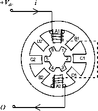 form a stator phase. In Fig. 27.97, the connected stator pole pairs are indicated by the same prefix letter. The general principle of operation of the SR motor is the same as all types of reluctance machines, i.e., the stator and the rotor poles seek the minimum-reluctance position, so that the stator excited flux becomes maximum. Hence, when current flows in an SR motor stator phase and produces a magnetic field, the nearest rotor pole will tend to position itself with the direction of the developed magnetic field. This position, which is termed the aligned position, is reached when the rotor pole center axis is aligned with the stator pole center axis (assuming symmetrical poles). The ahgned position also corresponds to the position of minimum reluctance, and hence the position of maximum inductance. It should be noted that the unaligned position is defined as the position when the interpole axis, or the axis of the center of the interpolar space in the rotor, is ahgned with a stator pole axis. This position corresponds to the position of minimum inductance. These rotor axis positions are illustrated in Fig. 27.98. To achieve continuous rotation, the stator phase currents are switched on and off in each phase in a sequence according to the position of the rotor. Consider the motor schematic illustrated in Fig. 27.97. If coils Al and A2 of phase A are excited and produce a magnetic field in a vertical direction, then poles 1 and 4 on the rotor will align themselves with the stator poles of phase A. If the coils of phase A now have their current switched off, and coils Bl and B2 of phase В are now excited, then in a similar fashion the rotor will move so that poles 2 and 5 are ahgned with stator poles Bl and B2. Exciting phases A, B, C, and D in sequence will produce rotor rotation in the counterclockwise direction. From the preceding discussion, one may see that the switching on and off of excitation current to the motor phases is related to the rotor pole positions. This means that some form of position sensor is essential for the effective operation of the SR motor. 27.9.2 Advantages and Disadvantages of Switched-Reluctance Motors The SR motor has a number of inherent advantages that makes it suitable for use in certain variable-speed drive applications. Nevertheless, the motor also has some inherent disadvantages rotor pole centre axis TABLE 27.6 Advantages and disadvantages of SR drives Advantages Disadvantages  ...inter-pole axis Low-cost motor Robust motor construction Absence of brushes No motor short-circuit fault No shoot-through fauhs Ability to operate with faulted phase High torque-to-inertia ratio Unidirectional currents High efficiency Need for position measurement Higher torque ripple than other machine types Higher noise than other machine types Nonhnear and complex characteristics FIGURE 27.98 Rotor pole axis positions. that must be considered before choosing the motor for a particular application. In Table 27.6, the main advantages and disadvantages of the SR motor drive are summarized. 27.9.3 Switched-Reluctance Motor Variable-Speed Drive Applications The main application for SR motors is in variable-speed drive systems. One apphcation area has been general-purpose industrial drives where speed, acceleration, and torque control are desired. SR-motor-based industrial drives provide the advantages of a very wide range of operating speeds as well as high efficiency and robustness. Other applications of the SR drive include automotive apphcations, where the SR motor has advantages of robustness and fault tolerance. The SR motor in this application can also be easily controlled for acceleration, steady speed, and regenerative braking. The SR motor is also well suited to aerospace applications where the ability to operate under faulted conditions and its suitability for operation under harsh environments are critical. Additionally, the very high speed capability and high power density also make these motors well suited in the aerospace field. There are also many domestic appliances where cost is of primary concern. In these products, the SR motor can provide a low-cost solution for a brushless fully controllable motor drive. In addition, the motor can be used in battery-powered applications, where the motors high efficiency and ability to use a dc supply are important. 27.9.4 SR Motor and Drive Design Options The main components of the drive system are shown in Fig. 27.99. It is important to design the motor and drive together in an integrated manner. The main criteria that need to be considered in designing the components of the SR drive system will be discussed later. It will be seen that certain design choices, which may be advantageous for one component of the drive system, may bring about disadvantages in another component. This highhghts the need for a careful, integrated system approach to be taken when designing the drive system. 3 phase Controlled or Uncontrolled RECTIFIER DC link INVERTER Input Commands в- Measured Currents and Voltages CONTROLLER SR MOTOR  LOAD Position Feedback FIGURE 27.99 Main components of an SR drive. 27.9.4.1 Number of Motor Phases There are many possibihties in choosing the number of stator phases and rotor poles in SR motors. The simplest SR motor may consist of only one phase; however, to operate the motor in four quadrants (motoring or generating in both forward or reverse directions), at least three phases are required. The most common configuration to date has been the four-phase SR motor, which has eight rotor poles and six stator poles, as was shown in Fig. 27.97. 27.9.4.2 Maximum Speed The SR motor is capable of operating at very high speeds because of its robust rotor construction, and in most applications the maximum speed is hmited by the inverter switching speed and not hmited by the motor itself. The maximum speed of the SR motor is itself normally greater than 15,000 rpm for a standard SR motor. Fiowever, to determine the maximum drive speed, the controller and motor must be considered together. This is because the power electronic device switching speed is directly proportional to the commutation frequency, which is in turn proportional to the motor speed. The maximum switching frequency of the power devices must therefore be taken into account in the SR drive design. 27.9.4.3 Number of Power Devices In general, the number of switches per phase in SR motor drives wiU vary according to the inverter topology. A wide range of different SR drive circuits are available for SR drives, and these are detailed below. Circuits with only one switch per phase are possible; however, these have various disadvantages such as control restrictions, a need for extra windings, or higher switch voltages. Fiowever, with two switches per phase the motor is fully controUable in four quadrants and has completely independent motor phase control. Therefore, the maximum number of power switches required for the motor operation is normally 2q, where q is the number of phases. 27.9.4.4 Inverter Topology Types for SR Motors As was mentioned, the torque produced in the SR motor is independent of the direction of current flow in each motor phase. This means the inverter is only required to supply unidirectional currents into the stator windings. The three major circuit topology types that have been used each winding of an SR motor drives are shown in Fig. 27.100. As indicated in this figure, these are commonly termed the bifilar, split dc supply, and two-switch type inverter circuits. In the circuits shown in Fig. 27.100, only one or two switching components per phase are required. Other circuit topology types that use shared components between the motor phases have limitations in control flexibility. 27.9AA.1 Bifilar-Type Inverter Circuit In Fig. 27.100a, a drive circuit for a bifilar-wound SR motor is shown. The bifilar windings are closely coupled, with one winding being connected to a switching device while the other is connected to a freewheeling diode. Current is increased in the winding when the switching device closes. At turn-off, the current transfers to the secondary winding through transformer action, and the inductive energy flows back into the supply via the freewheeling diode. If perfect coupling is assumed, then the voltage across the switching device wiU rise to twice the dc supply voltage during turn-off. Fiowever, in practice this would be higher. This is because there wiU be some uncoupled inductance in the primary that wiU cause high induced voltages when the current in the winding coUapses to zero. Thus, snubbing circuits would almost certainly be required to protect the switching components from overvoltage. The advantage of the bifilar circuit is that it requires only one switching device per phase. Fiowever, with the advent of FIGURE 27.100 Major SR inverter topology types: (a) bifilar type; (b) split dc supply type; (c) two-switch type. modern power electronic devices, which have both low cost and low losses, this advantage quickly disappears. 27.9AA.2 Split dc Supply Inverter Circuit The split dc supply type inverter circuit shown is shown in Fig. 27.100b. As in the bifilar circuit, this configuration also uses only one switching device and one diode per phase. However, a center-tapped dc source is required. When the switching device is turned on, current increases in the phase winding because of the positive capacitor voltage being apphed. At turn-off, the current is forced to flow through the diode and thus decays to zero more quickly because of the connection to the negative voltage. It is usual for the dc center tap to be implemented using a split capacitor in the dc link. The voltages across each capacitor must remain balanced, which means that there can be no significant power-flow difference between the two capacitors. Upon examination of the circuit, it can be seen that because of the split capacitor bank, only half the available dc voltage can be switched across the phase winding. Thus, for the same voltage across the motor phases that is supplied by the bifilar circuit earlier, the dc supply voltage must be doubled with respect to the bifilar circuit supply. This means that the voltage rating of the devices would effectively be the same as in the bifilar circuit. This is inherently inefficient. The configuration also has the need for balanced split capacitive components. In addition, it will be seen that the soft-chopping form of control described in Section 27.9.7 is not available in this drive. 27.9AA.3 Two-Switch Inverter Circuit The two-switch inverter type circuit, which is shown in Fig. 27.100c, uses two switching devices and two diodes per phase. Unlike the previous two circuits, three modes of operation are possible: Mode 1: Positive phase voltage. A positive phase voltage can be applied by turning both switching devices on. This will cause current to increase in the phase winding. Mode 2: Zero phase voltage. A zero voltage loop can be imposed on the motor phases when one of the two switches is turned off while current is flowing through the phase winding. This results in current flow through a freewheeling loop consisting of one switching device and one diode, with no energy being supplied by or returned to the dc supply. The current will decay slowly because of the small resistance of the semiconductors and connections, which leads to small conduction losses. This mode of operation is used in soft chopping control, as described in Section 27.9.7. Mode 3: Negative phase voltage. When both switches in a motor phase leg are turned off, the third mode of operation occurs. In this mode, the motor phase current will transfer to both of the freewheeling diodes and return energy to the supply. When both of the diodes in the phase circuit are conducting, a negative voltage with amplitude equal to the dc supply voltage level is imposed on the phase windings. In this circuit the switching devices and diodes must be able to block the dc supply voltage amplitude when they are turned off, in addition to any switching transient voltages. However, because the circuit contains two devices in series, the blocking voltage is essentially half the value seen in the previous two circuit types for the same applied motor phase voltage amplitude. Another advantage of the two-switch inverter circuit is that it offers greater control flexibility with its three modes of voltage control. A disadvantage of this inverter type, as compared to the bifilar and split dc supply types, is that it contains twice as many switching components per phase. However, with the current wide availability and economy of power semiconductors, in most applications the advantages of the two-switch circuit outweigh the cost of an extra switching device per phase. 27.9.5 Operating Theory of the Switched-Reluctance Motor: Linear Model If a linear magnetic circuit is assumed, the flux linkage is proportional to phase current for any rotor position 0. This is demonstrated in Fig. 27.101, where the magnetization curves for the linear SR motor for various rotor positions and currents are shown. In this hnear case, the inductance L at Flux Linkage (Wb)  Aligned Position Rotor Position 9 (degrees) Unaligned Position Current / (A) FIGURE 27.101 Magnetization characteristics of linear SR motor. any position в, which is the slope of these curves, is constant and independent of current. As the motor rotates, each stator phase undergoes a cychc variation of inductance. As can be seen in Fig. 27.101, in the fully aligned position (when a rotor pole axis is directly ahgned with the stator pole axis) the reluctance of the magnetic circuit through the stator and rotor poles wiU be at a minimum, and thus the inductance of the stator winding wiU be at a maximum. The opposite will occur in the fully unaligned position (when the rotor interpole axis is aligned with the stator pole). Thus, the inductance becomes a function of position only and is not related to the current level. If it is also assumed that mutual inductance between the phases is zero, then a typical inductance variation 1(6) with respect to rotor position similar to that shown in Fig. 27.102 arises. Although this is an idealized inductance variation, it is helpful in the understanding of key operating principles of the machine. One should note that in the idealized inductance variation there are sharp corners, which can only arise if flux fringing is completely ignored. Four distinct regions can be identified in the plot of the linear inductance variation shown in Fig. 27.102. These distinct regions correspond to a ranges of rotor pole positions relative to the stator pole positions as be described below: Region A. This region begins at rotor angle 9i, where the first edge of the rotor, with respect to the direction of rotation, just meets the first edge of the stator pole. The inductance will then rise in a linear fashion until the poles of the stator and rotor are completely overlapped at angle 02- At this point, the magnetic reluctance is at a minimum and the phase inductance is at a maximum. These rotor positions are illustrated in Figs. 27.103a and 27.103b for an example four-phase motor with rotor pole 1 approaching the stator pole of phase A. Region B. This region spans from rotor positions 62 to 9. In this region, the inductance remains constant because the rotor pole is completely overlapped by the stator pole (i.e., the overlap area of the poles remains constant). At rotor angle 6 the edge of the rotor pole leaves the stator pole overlap region, and thus the area of overlap wiU again begin to decrease. The position at which this occurs is illustrated in Fig. 27.103c. Region C. When the rotor moves past 0, the rotor pole leading edge begins to leave the pole overlap region, and region С begins. At this point, the inductance begins to hnearly decrease, until at 9, the rotor pole has completely left the stator pole face overlap region. At this point the inductance is at its minimum once more. The rotor L max Torque T T max T min - A В Constant Current / Direction of rotation Direction of rotation 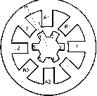 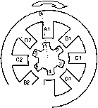 Direction of rotation Direction of rotation 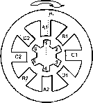 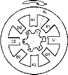 FIGURE 27.103 Rotor pole 1 positions, (a) Meeting edge of stator pole A. (b) Overlapped by stator pole A. (c) Edge of rotor pole leaving overlap region, (d) Rotor pole completely leaving overlap region. (Note: Airgap space is exaggerated for clarity.) position at which the rotor pole has completely left the overlap is indicated in Fig. 27.103d. Region D. In this region the rotor and stator have no overlap, and thus the inductance remains constant, at the minimum level, until region A is reached once again. It was mentioned earlier that when a stator phase is excited, the rotor poles will tend to move toward the maximum-inductance region. Thus, a motoring torque is produced when a stator phase is provided with a current pulse during the angles when the inductance is rising (assuming motoring rotation is in the direction of increasing в in Fig. 27.102. This means that if positive torque is desired, excitation should be arranged such that current flows between the appropriate rotor angles when the inductance is rising. Conversely, if current flows during the decreasing inductance region, a negative torque would resuh. This is because the rotor will be attracted to the stator pole in such a way that it rotates in the opposite direction to the motoring rotation, or in other words, the rotor experiences a torque opposite to the direction of rotation. It should be noted that this reluctance machine torque always acts to decrease the reluctance. The direction of current flowing into the stator winding is irrelevant. This signifies that unidirectional current excitation is possible in the SR motor drive. The variation of torque with rotor angle for a constant phase winding current is as shown in Fig. 27.102. It can be seen that the torque is constant in the increasing and decreasing inductance regions, and is zero when the inductance remains constant. The preceding physical explanation of the developed torque is also given by the famihar torque equation (27.96) for a variable-reluctance machine 1.2 dm (27.96) From (27.96) it is evident that the magnitude of the instantaneous torque developed in the SR motor is proportional to both i2 and dL/dO. If the inductance is increasing with respect to the angle, and current flows in the phase winding, then the torque will be positive and the machine will operate in motoring mode. Hence, from Eq. (27.96) it can be seen that when the motor phase is excited during a rising inductance region, part of the energy from the supply is converted to mechanical energy to produce the torque, and another part is stored in the magnetic field. If the supply is turned off during this region, then any stored magnetic energy is partly converted to mechanical energy and partly returned to the supply. However, a negative or braking torque will be developed by the motor if the inductance is decreasing with respect to the rotor angle and current flows in the phase winding. In this case energy flows back to the supply from both the stored magnetic energy and the mechanical load, which acts as a generator. It can also be seen from Eq. (27.96) that the sign (or direction) of the torque is independent of the direction of the current and is only dependent on the sign of dL/dO. This explains the torque waveforms that were seen in Fig. 27.102, where for constant current (and constant dL/dO magnitude), the magnitude of the torque was constant in the rising or decreasing inductance regions. However, it was seen that the torque changes from positive to negative according to the sign of dL/de. Hence, the ideal waveform for the production of motoring torque would be a square-wave pulse of current (with magnitude equal to the maximum possible supply current) flowing only during the increasing inductance period. This current waveform is illustrated in Fig. 27.104b. However, in practice this type of current waveform is difficult to produce in a motor phase. This is because the motor phase current is supplied from a finite dc voltage source, and thus inductance of the stator phase winding would delay the rise and fall of current at the pulse edges. Instead, a more practical current waveform is normally used as is illustrated in Fig. 27.104c. It can be seen that in this waveform the ideal square waveform is 1 ... 69 70 71 72 73 74 75 ... 91 |
|
© 2026 AutoElektrix.ru
Частичное копирование материалов разрешено при условии активной ссылки |