 |
 |
 |
| Главная Журналы Популярное Audi - почему их так назвали? Как появилась марка Bmw? Откуда появился Lexus? Достижения и устремления Mercedes-Benz Первые модели Chevrolet Электромобиль Nissan Leaf |
Главная » Журналы » Metal oxide semiconductor 1 ... 70 71 72 73 74 75 76 ... 91 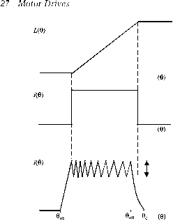 hysteresis band (с) F(0) 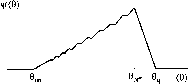 FIGURE 27.104 (a) Linear phase inductance variation, (b) Ideal square-wave phase current, (c) Chopping-mode phase current, (d) Chopping-mode phase voltage, (e) Flux linkage waveform corresponding to chopping-mode current. 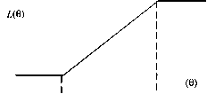 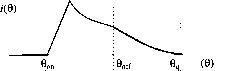 F(e) 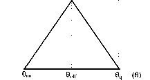 FIGURE 27.105 (а) Linear phase inductance variation, (b) Single-pulse-mode phase current, (c) Single-pulse-mode phase voltage, (d) Flux linkage waveform corresponding to single-pulse-mode current. closely approximated by the use of hysteresis current control. At higher speeds hysteresis current control can no longer be used and a current waveform similar to that shown in Fig. 27.105b is seen in the phase winding. These two types of practical current waveforms, which approximate the ideal square-pulse waveform (a) at low to medium speeds and (b) at high speeds, wiU be discussed next. 27.9.5.1 Low- to Medium-Speed Approximation to Square-Pulse Current Waveform At low to medium motor speeds, the ideal square-pulse current waveform is approximated in the practical motor drive using hysteresis current control, as is shown in Fig. 27.104c. The hysteresis method of controlling the current is termed the chopping-mode control method in SR motor drives. During the time of conduction (between the turn-on and turn-off angles), the current is maintained within the hysteresis band by the switching off and on of the phase voltage by the inverter when the phase current reaches the maximum and minimum hysteresis band. An example of the voltage waveform used for the hysteresis current control is shown in Fig. 27.104d, where a constant inverter dc supply voltage of magnitude is used. It can be seen that the switching frequency of the voltage waveform decreases as the angle increases. This is due to the fact that the phase inductance is hnearly increasing with angle, which has the effect of increasing the current rise and fall time within the hysteresis band. In the chopping-mode control method, the turn-on region is defined as the angle between the turn-on angle 6 and the turn-off angle 0, and is chosen to occur during the rising inductance region for motoring torque. In the practical chopping current waveform, the current turn-on angle 0 is placed somewhat before the rising inductance region. This is to ensure that the current can quickly rise to the maximum level in the minimum-inductance region before the rising-inductance, or torque-producing, region. Similarly, the turn-off angle 9ff is placed a little before the maximum inductance region so that the current has time to decay before the negative-torque, or decreasing-inductance, region. The angle at which the current decays to zero after turn-off is labeled as in Fig. 27.104c. 27.9.5.2 High-Speed Approximation to Square-Pulse Current Waveform The chopping mode of operation cannot be used at higher speeds, as at these speeds the hysteresis band current level will not be reached. This is because at high speeds the back emf of the motor becomes equal to or larger than the voltage supply in the rising-inductance region, which limits the increase of the motor phase current. In addition, the rise time of the current will correspond to an ever-increasing angle as the speed is increased. Eventually, at high speeds, the rise-time angle will be so large that the turn-off angle 9 will be reached before the hysteresis current level has been exceeded. Thus, at high speeds the current is switched on and off only once per cycle. In SR motor drive control, this is called the single-pulse mode of operation. An example of the single-pulse mode current is illustrated in Fig. 27.105b. In the single pulse mode of operation, the inverter power switches turn on at rotor angle which places the dc voltage supply across the phase winding, as is shown for the example single-pulse voltage waveform in Fig. 27.105c. As for the chopping-mode case, in order to maximize torque 6 must usually be located prior to the rising inductance region. This is so that, while the inductance is low, the current has a chance to rise rapidly to a substantial value before the torque-producing region begins and the motor back emf increases. At rotor angle 9, the power switches are turned off, and the phase will have a negative voltage (typically -thrown across it. The current will then decay until it becomes zero at rotor angle 9. 27.9.6 Operating Theory of the SR Motor (II): Magnetic Saturation and Nonlinear Model In the hnear model described earlier, it was assumed that the inductance of a phase winding is independent of current. However, in a real SR motor significant saturation of the magnetic circuit normally occurs as the phase current increases, and thus the phase inductance is related to both the phase current level and position. Because of the magnetic saturation effect, the actual phase inductances at a given rotor position can be reduced significantly compared to the inductance given by linear magnetization characteristics. In addition, the effect of magnetic saturation becomes larger as the motor current level increases. The effects of saturation in an SR motor can be observed in a plot of its magnetization curves. This shows the relationship of flux linkage versus current, at rotor positions varying between the fully aligned and unaligned angles. A typical set of SR motor magnetization curves is shown in Fig. 27.106, where it can be seen that there is a nonlinear relationship between the flux linkage and current for each curve. 0.8 -0.7 -0.6 Flux Linkage 0.5 -(Wb) 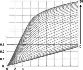 Rotor Angle (degrees) 6 8 10 12 14 16 18 Current (A) Because of the magnetic saturation effect discussed earher, the instantaneous torque equation (27.96), which was derived assuming hnear conditions, will not be generally valid for calculating the torque in SR motors. Therefore, for accurate calculations, the torque must take into account the dependence of phase inductance with current and position. If one considers the phase inductance saturation, the expression for instantaneous torque production of an SR motor phase can be written as (27.97) J 1=constant where the coenergy W is defined as (27.98) 27.9.7 Control Parameters of the SR Motor A variety of performance characteristics can be obtained in the SR motor by controlling various parameters. These parameters include the chopping-mode control hysteresis level at low to medium speeds, and the turn-on and turn-off angles 9 and 9 at aU motor speeds. By controlhng these parameters it is possible to produce any desired characteristic such as constant torque, constant power, or some other particular characteristic in between. As discussed in Section 27.9.5, two distinct modes of operation apply in the SR motor depending on the nature of the current waveform. These modes are the chopping-mode control, which can be used at low to medium motor speeds, and the single-pulse mode of control, which is used at high speeds. Both of these modes of operation wiU be further detailed hereafter, with an explanation of the corresponding inverter switching operation. 27.9.7.1 Chopping-Mode Control In the chopping-mode control region, the turn-on and turn-off angles are controlled together with the current level. As described in Section 27.9.5, the turn-on angle and turn-off angle are controlled so that current flows during the rising-inductance or positive torque-producing region. This normally means that the turn-on angle is placed shortly before the place where the rising inductance angle begins, and the turn-off angle is placed shortly before this region ends. In the chopping mode, the current level is controUed to remain below the maximum aUowable level. This involves switching the voltage across the phase on and off in such a manner that the current is maintained between some chosen upper and lower hysteresis current levels. An example of this form of current chopping control was shown in Fig. 27.104c.  О о FIGURE 27.107 Soft chopping mode conduction paths: (a) both devices on-positive voltage applied to motor phase; (b) Tl turned off-zero-voltage freewheeling loop applied to motor phase. The actual torque production of the motor in the chopping mode is set by the control turn-on and turn-off angles and the current hysteresis level. Within the chopping mode of operation, two current hysteresis control schemes can be used. These are termed soft and hard chopping. Soft chopping can only be used in some circuit configurations, such as that shown in Fig. 27.107. For soft chopping control one switching device remains on during the entire conduction period whUe the other is switched on and off to maintain the desired current level. This can be seen in Figs. 27.107a and 27.107b, where the two conduction modes during chopping are shown. When both switches are on, the phase winding receives the fuU positive supply, whereas when only one switching device is on, the phase experiences a zero-voltage freewheeling loop that wiU decrease the current. In the hard-chopping scheme, both devices are switched simultaneously and have the same switching state at aU times. If both switching devices are turned on, the phase winding sees the fuU positive supply. To decrease the current, the fuU negative supply is applied by turning both devices off as shown in Fig. 27.108. In circuit configurations with fewer than two switches per phase, only hard chopping can be used. Soft chopping is more advantageous than hard chopping. This is because of a smaUer dc ripple current in the supply, which can substantially minimize the ripple-current rating of the dc link capacitor, as weU as lower the hysteresis loss in the motor. It has also been found that soft chopping lowers acoustic noise and electromagnetic radiation. 27.9.7.2 Single-Pulse Mode Control At higher speeds, the back emf of the SR motor eventually becomes greater than or equal to the supply voltage during the rising-inductance region. This means that even if a phase is excited, the current in the motor phase wiU not increase in the rising inductance region. Therefore, at higher speeds the turn-   О FIGURE 27.108 Hard chopping mode conduction paths: (a) both devices on-positive voltage apphed to motor phase; (b) Tl and T2 turned off-negative voltage apphed to motor phase. on angle must be placed before the beginning of the increasing inductance region, so that the phase current will have an adequate time to increase before the back emf becomes high. In addition, the time available for the current to rise after turn-on becomes less and less as the speed of the motor increases. This is due to the fact that the available conduction time is lower for constant switching angles as the speed of rotation increases. This can be seen by considering that speed is the time rate of change of angle. Thus, as the speed increases, there will be a point when the current level never rises to the chopping level. At this point, the single-pulse mode of operation will come into effect and the current will decrease or remain constant throughout the increasing inductance zone. An example of a single-pulse-mode current waveform was seen in Fig. 27.105b. As the current is not commutated in the single-pulse mode, the control in this mode consists only of controlling the on and off angles. The turn-on angle 0 can be placed at some point in advance of the rising-inductance region where the phase inductance is low, so that current can increase at a faster rate before the increasing-inductance region. The angle can be advanced up until maximum allowable current occurs at the peak of the waveform (this may even mean switching on in the previous decreasing inductance zone). The actual control turn-on and turn-off angles for the single-pulse mode, for a given load torque and speed, can be determined by simulating the motor equations. The speed at which changeover between single-pulse and chopping mode occurs is called the base speed. Base speed is defined as the highest speed at which chopping mode can be maintained at the rated voltage and with fixed on and off angles. Below the base speed, the current increases during the rising-inductance region, unless it is maintained at the maximum or a lower level by chopping. Therefore, it can be seen that at lower speeds that are below the base speed, the motor is controlled using chopping-mode control, whereas at speeds above the base speed the single pulse mode of control is used. In both control modes the control turn-on and turn-off angles are chosen so that the motor provides the required load torque. 27.9.8 Position Sensing It can be seen from the preceding discussion that to control the SR motor satisfactorily, the motor phases are excited at the rotor angles determined by the control method. It is therefore essential to have knowledge of the rotor position. Furthermore, the rotor angle information must be accurate and have high resolution to allow implementation of the more sophisticated nonlinear control schemes that can minimize torque ripple and optimize the motor performance. This means that the performance of an SR drive depends on accurate position sensing. The efficiency of the drive and its torque output can be greatly decreased by inaccurate position sensing, and corresponding inaccurate excitation angles. It has been demonstrated that at high motor speeds an error of only 1° may decrease the torque production by almost 8% of the maximum torque output. Traditionally, rotor-position information has been measured using some form of mechanical angle transducer or encoder. The position-sensing requirements are in fact similar to those for brushless PM motors. However, although position sensing is required for the motor operation, position-measurement sensors are often undesirable. The disadvantages of the electromechanical sensors include the following: (a) The position sensors have a tendency to be unrehable because of environmental factors such as dust, high temperature, humidity, and vibration. (b) The cost of the sensors rises with the position resolution. Hence, if high-performance control is required, an expensive high-resolution encoder needs to be employed. (c) There is an additional manufacturing expense and inconvenience due to the sensor installation on the motor shaft. In addition, consideration must be given to maintenance of the motor because of the mechanical mounting of the sensors, which also adds to the design time and cost. (d) Mechanical position sensors entail extra electrical connections to the motor. This increases the quantity of electrical wiring between the motor and the motor drive. This wire normally needs to be shielded from electromagnetic noise and thus further adds to the expense of the drive system. (e) The allocation of space for the mounting of the position sensor may be a problem for small applications (such as for motors used in consumer products). Hence, to overcome the problems induced by rotor-position transducers, researchers have developed a number of methods to ehminate the electromechanical sensor for deriving position information. This is achieved by indirectly determining the rotor position. Such methods are commonly termed sensorless rotor-position estimation methods. The term sensorless seems to imply that there are no sensors at aU. However, there must be some form of sensor used to measure the rotor position. In fact, the term sensorless position estimation in reality imphes that there are no additional sensors required to determine position apart from those that measure the motor electrical parameters to control the motor. These are normally current-or voltage-measuring circuits. Hence, all sensorless position estimation methods for the SR motor use some form of processing on electrical waveforms of the motor windings. In essence, the major difference between sensorless position detection, and the electromechanical sensors mentioned above, is that there is no mechanical connection of the sensor to the motor shaft. Therefore, the sensorless position detection involves electrical measurements only. 27.9.9 Further Reading 1. J. R. Hendershot, Application of SR drives, IEEE IAS Tutorial on Switched Reluctance Drives, IEEE Industrial Applications Society, pp. 60-90, 1990. 2. R J. Lawrenson, Switched reluctance motor drives, Electronics and Power, 144-147, Feb. (1983). 3. E. Richter, Switched reluctance machines for high performance operations in a harsh environment-a review paper, Int. Conf. Electrical Machines (ICEM90), Part 1, pp. 18-24, Aug. (1990). 4. R J. Lawrenson, Switched reluctance drives-a fast growing technology, Electric Drives and Controls, April/May (1985). 5. T. J. E. Miller, Switched Reluctance Motors and Their Control. Clarendon, Oxford, 1993. 6. S. R. MacMinn, Control of the switched reluctance machine, Switched Reluctance Drives Tutorial, IEEE Industry Applications Society Conference, 25th IAS Annual Meeting, Seattle, October 12, pp. 36-59 (1989). 7. A. D. Cheok and N. Ertugrul, High robustness of an SR motor angle estimation algorithm using fuzzy predictive filters and heuristic knowledge based rules, IEEE Trans. Ind. Electr, 46:5 (1999). 27.10 Synchronous Reluctance Motor Drives Robert Betz 27.10.1 Introduction In recent years there has been a revival of interest in reluctance machines. Two main machines have been the focus of this interest-the switched-reluctance machine (SRM) and the synchronous reluctance machine (Syncrel). The SRM is a machine that does not have sine-wave spatial distributed windings, but instead has concentrated coils and a doubly sahent rotor and stator structure. The operation of this machine is highly nonlinear in character, and normal ac machine modeling techniques cannot be applied in a straightforward manner to describe its operation. The SRM drive has been considered in detail in an earher section. The Syncrel, on the other hand, has conventional three-phase sinusoidally distributed windings on the stator. The word synchronous in the machines name emphasizes the fact that the stator windings generate a spatial sinusoidally distributed magnetomotive force (mmf) in the airgap between the stator and the rotor, and under steady-state conditions the rotor rotates in synchronism with this field. Therefore, the stator winding configuration of this machine is virtually exactly the same as that of the induction machine or the conventional synchronous machine. The major difference between the Syncrel and conventional synchronous and induction machines is in the rotor structure. In both the induction machine and the synchronous machine, there is a source of flux in the rotor itself. In the case of the induction machine, this flux is produced by currents resulting from an induction mechanism, and for the synchronous machine there is a field winding wound on the rotor that is fed with dc current to produce flux. The permanent magnet synchronous machine replaces the wound field on the rotor with a permanent magnet. The Syncrel, on the other hand, does not have any source of flux on the rotor, but instead the rotor is designed to distort the flux density distribution produced by the sinusoidally distributed mmf. Sinusoidally wound reluctance machines were traditionally used in the fiber-spinning industry because of their synchronous nature. This made it simple to keep a large number of machines running at the same speed using just the frequency of the supply to the machines. These machines were direct-online-start machines. This was facilitated by the presence of an induction machine starting cage on the rotor. This cage was also essential to damp out oscillations in the rotor speed when running at synchronous speed. It should be pointed out that these machines are not considered to be Syncrels-a Syncrel does not have an induction machine cage on the rotor. A Syncrel is absolutely dependent on an inteUigent inverter drive in order to start the machine and to stabUize it when running. The lack of a requirement for a starting cage means that the rotor design can be optimized for best torque and power performance. The revival of interest in the Syncrel in the early 1980s was motivated by the development of low-cost microprocessors and reliable power electronics, coupled with the perception that the Syncrel may be more efficient and simpler to control in variable-speed applications compared to the induction machine. The control simphcity is achieved in practice mainly because one does not have to locate the flux vector in order to implement vector control. The potential for improved efficiency and torque density compared to the induction machine is very dependent on the rotor design. The Syncrel has the advantage over the switched-reluctance machine in that it produces relatively smooth torque naturally, and it uses a conventional three-phase inverter. Therefore, inverter technology developed for the induction machine can be applied directly. 27.10.2 Basic Principles Reluctance machines are one of the oldest electric machine structures, since they are based on the basic physical fact that a magnet attracts a piece of iron. In fact, Syncrel structures were being pubhshed in the early 1920s [1]. The essential idea behind the operation of all reluctance machines is that the windings of the machine produce magnetic poles that are used to attract the reluctance rotor. If the magnetic poles are moved around the periphery of the machine at the rate at which the rotor is moving, then sustained torque and rotation can be achieved. A conceptual diagram of a Syncrel is shown in Fig. 27.109. In this figure the rotor is represented as a simple dumbbell - type rotor. The axes of the three-phase sinusoidally distributed windings are indicated by the dashed lines. If these windings are being fed with currents, then a spatial sinusoidally distributed mmf results. Because this mmf is sinusoidally distributed it can be represented by a space vector (similar to sinusoidal time-varying quantities being represented by a time phasor). In Fig. 27.109, this resultant space vector is indicated by F- F and Fq are the components of this vector that lie along the high-permeance and low-permeance axes of the machine, respectively. If one considers the situation shown in Fig. 27.109, then the rotor would tend to rotate in the direction indicated. This rotation would continue until the high-permeance axis (i.e., the least-reluctance axis) of the machine ahgns with the mmf vector. When this ahgnment occurs, the flux produced by the stator mmf vector would be maximized. If the F vector also rotates as the rotor rotates, then as mentioned previously, the angle between F and d will remain constant and the rotor will continue to chase the F vector, continuous rotation being the result. One can ask even more fundamental questions, such as, why does the rotor rotate to the position that maximizes the flux density? This is essentially asking, why does a magnet attract a piece of iron? To completely answer this question one 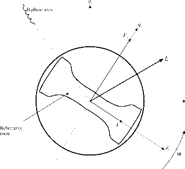 A phase axis С phase axis Д has to delve into the field of quantum physics, which is beyond the scope of this presentation. A less complicated explanation is based on the fact that the stator flux density tends to align the domains in the ferromagnetic rotor material, which produces an effect similar to having a current-carrying winding wrapped around the rotor. This effective current then interacts with the stator flux density to produce a force that has a component that is oriented radially around the periphery of the machine. It is this component that produces the torque on the rotor that causes the alignment with the stator mmf vector. It was mentioned previously that in order to have continuous motion, the mmf vector F must rotate at the same angular velocity as the rotor so that the angle between the mmf vector and the axis of the rotor is kept at a constant value. The rotation of the mmf vector is achieved by feeding the three-phase windings of the machine with time-varying currents. It can be shown that if these form a balanced 120° temporally phase-shifted set of sinusoidal currents, then the resultant mmf vector wiU rotate at a constant velocity related to the frequency of the input current waveforms and the number of pole pairs in the machine. In order to get a more precise figure for the torque produced by a Syncrel, one has to develop techniques of modeling the machine. Because the Syncrel is a reluctance machine, the coenergy technique for developing the torque expressions can be used [2,3]. The coenergy technique is a very accurate way of determining the torque as it explicitly takes into account the saturation nonhnearities in the iron of the machine. However, the technique does not lend itself to mathematical analysis and is not a good way of understanding the basic dynamic properties of the machine. The coenergy approach wiU not be pursued any further in this presentation. 27.10.3 Machine Structure The essential difference between the Syncrel and, say, the induction machine is the design of the rotor. Most experimental Syncrel systems that have been built use the stator of an induction machine, including the same windings. The rotor designs can take on a number of different forms, from the very simple and basic dumbbeU-shaped rotor (such as that sketched in Fig. 27.109) to more complex designs. Unfortunately, the designs that are simple to manufacture (such as the dumbbeU design) do not give good performance; therefore, one is forced into more complex designs. The design of the rotor in a Syncrel is the key to whether it is economic to manufacture and has competitive performance with similar machines. The design of Syncrel rotors fall into four main categories of increasing manufacturing complexity and performance: dumbbeU or higher pole-number equivalent designs, flux-barrier designs, radially laminated flux-barrier designs, and axially laminated designs. The first two of these design methodologies are old and lead to designs with poor to modest performance. Therefore, they wiU not be considered Q-axis Narrow iron bridge D-axis 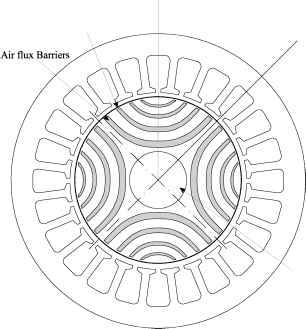 Shaft FIGURE 27.110 Cross section of a radially laminated Syncrel. any further. The latter two, however, lead to machine designs with performance comparable to that of the induction machine. Figures 27.110 and 27.111 show the cross section of a four-pole machine with a radial lamination flux-barrier designed Q-axis Pole -piece Lamination Inter-lamination space D-axis  Shaft rotor and an axially laminated rotor. The radial lamination design allows the rotor to be built using similar techniques to standard radial laminations for other machines. The flux barriers can be punched for mass production, or wire eroded for low production numbers. These laminations are simply stacked onto the shaft to form the rotor. The punched areas can be filled with plastic or epoxy materials for extra strength if required. The iron bridges at the outside of the rotor are designed to saturate under normal flux levels and therefore do not adversely affect the performance of the machine. They are there to provide mechanical strength. The axially laminated rotor is constructed with laminations running the length of the rotor (i.e., into the page on Fig. 27.111). In between the laminations a nonmagnetic packing material is used. This can be aluminum or bronze, for example, but a nonconductive material such as slot insulation is better since eddy currents can be induced in conductive materials. The ratio of the steel laminations to nonmagnetic material is usually about 1:1. The axial laminations are all stacked on top of each other, and a nonmagnetic pole piece is bolted on top of the stack to hold the laminations to the shaft. The strength of these bolts is usually the main limitation on the mechanical strength and hence speed of rotation of this rotor. If more or thicker bolts are used to increase strength, the magnetic properties of the rotor are compromised because of the amount of lamination that has to be cut out to make room for them. Radial and axial laminated rotors are usually limited to four-pole or higher machines because of the difficulty of accommodating the shaft in two-pole designs. An axially laminated two-pole rotor has been built with the shafts effectively bonded onto the end of the rotor. Another design was constructed of a block of alternating steel and bronze laminations, the whole structure being brazed together and the resultant stack then being machined into a round rotor and shafts (this rotor was used for high-speed generator applications). Of the two rotor designs, the radially laminated one has the best potential for economic production. The axially laminated rotor in general gives the best performance, but the mass production difficulties with folding and assembling the laminations make its adoption by industry unlikely. On the other hand, improved designs for radially laminated rotors mean that they can now produce performance very close to that of the axial laminated designs, and the ease of manufacture would indicate that these rotors are the future of Syncrel rotors. 27.10.4 Basic Mathematical Modeling In order to give a more quantitative understanding of the machine, a basic mathematical dynamic model of the machine will be introduced. This model will assume that the iron material in the machine does not saturate. This means that the flux density and flux linkage of the windings in the machine are linear functions of the currents in the machine. To derive the electrical dynamic model of a machine, one usually uses Faradays flux-linkage expressions. In the case of the Syncrel, the self and mutual flux linkage between the phases is obviously a function of the angular position of the rotor; therefore, one needs to have expressions for these inductances in terms of rotor position. The fundamental assumption used to make this mathematically tractable is that the inductances vary as a sinusoidal function of the rotor position. The other major part of the modeling process is the conversion from a three-phase model to a two-phase model. This is a process that is carried out for most sinusoidally wound machines, since it allows a variety of machines to be represented by very similar models. A further complication in this process is that the two-phase model is derived in a rotating reference frame, as opposed to a stationary reference frame. Developing the equations in a rotating reference frame has the advantage that the normal sinusoidal currents feeding the machine are transformed into dc currents in steady state, and the angular dependence of the machines inductances disappear. One way of heuristically understanding the effect of the rotating-frame transformation is to imagine that we are observing the machines behavior from the vantage point of the rotor. Because the sinusoidal flux density waveform is rotating around the machine in synchronism with the rotor, it appears from the rotor that the flux density is not changing with time-i.e., it is a flux density created by dc currents flowing in a single sinusoidally distributed winding. This single sinusoidal winding is effectively rotating with the rotor. It should be noted that the transformation process of the fluxes, currents, voltages, and machine parameters to the two-phase rotating frame is an invertible process; therefore, one can apply the inverse transformation to ascertain what is happening in the original three-phase machine. The models derived using the three-phase to two-phase transformations are known as dq models, the d and q referring to the two axes of the machine in the two-phase model (both stationary and rotating frame dq axes are shown in Fig. 27.109). The linear dq equations for the Syncrel can be derived as [4] v, = Ri,L,-CDLi (27.99) q = Rk + L + ojL,i, (27.100) The sinusoidal variation of inductance with rotor position turns out to be very accurate because the stator windings are sinusoidally wound. This forces the flux hnkage to behave in a sinusoidal fashion. Linear refers to the fact that the equations are derived assuming that the iron circuit behaves linearly in relation to applied mmf and the flux produced. id R (OLqiq coLdid FIGURE 27.112 Two-phase equivalent circuit of the Syncrel in a rotating frame. where v, = the d-axis voltage and current Vq, iq = the d-axis voltage and current L, Lq = the d- and -axis inductances, respectively cd = the electrical angular velocity of the rotor Thus far we have concentrated on the electrical dynamics of the machine. The other very important aspect is the torque produced by the machine. It is possible to derive the torque of the Syncrel using the principle of virtual work based on coenergy as Te = Pp(Ld-Lq)idi, (27.101) The 3/2 factor is to account for the fact that the two-phase machine produces two-thirds the torque of the three-phase machine. The only other remaining equation is the mechanical equation for the system: -h Deo, + = (27.102) where / = the rotational inertia of the rotor/load D = the friction coefficient for the load Tp = the fixed load torque of the load = the rotor mechanical angular velocity (= co/pp) Remark. Equation (27.101) shows that the machine must be designed so that - is as large as possible. This will maximize the torque that is produced by the machine for given d- and q-axis currents. To lower one must design the q-axis so that it has as much air obstructing the flow of flux as possible, The 3/2 conversion factor is required if the transformations are power-variant transformations, as opposed to the power-invariant transformations. The power-variant transformations are the most common ones used because the single-phase machine parameters can be used directly in the resultant models, and the two-phase voltages and currents are identical in magnitude to their three-phase counterparts. and the d-axis must be designed so that it has as much iron as possible. In practice these quantities cannot be varied independently. Figure 27.112 shows the equivalent circuit for the Syncrel corresponding to Eqs. (27.99) and (27.100). One can see that the dynamic equations for the Syncrel are intrinsically simple. In contrast, the induction machine electrical equations consist of a set of four complex coupled differential equations. 27.10.5 Control Strategies and Important Parameters The dq model captured in Eqs. (27.99)-(27.101) can be used to explain a number of control strategies for the Syncrel. It is beyond the scope of this section to present the derivation of these. The interested reader should consult references [4-6] cited at the end of this section. One of the most common control strategies for any electrical machine is to maximize the torque per ampere of input current. The following discussion should be considered in conjunction with Fig. 27.113, which shows the relationship of the various vectors in the machine to the dq and dq axes. It turns out that one of the critical parameters for the control of the Syncrel is the angle of the resultant current 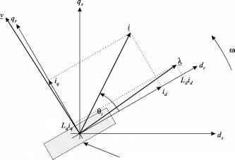 Rotor vector in the machine in relation to the d-axis of the machine. It is possible to write the torque expression for the Syncrel in terms of this as T, = -p(L,-L)\i\sm23 (27.103) It is obvious that this expression is maximized for a given value of i if = я/4. Therefore, one should control the currents so that 3 stays at this angle if maximum torque per ampere is desired. Another control objective for the Syncrel is to maximize the power factor for the machine. This is important to minimize the kVA for the inverter. It can be shown that the current angle to maximize the power factor is [4] where 3 = tan- = L/L (the inductance ratio) (27.104) Remark. Equation (27.104) indicates that is the important parameter in relation to power factor. In order to obtain a power factor of 0.8, one requires an inductance ratio of approximately 10. Finally, we shall consider another control objective- maximize the rate of change of torque with a fixed-current-angle control strategy. In effect this means that one is maximizing the rate of change of the currents in the machine for a given voltage applied to it. The analysis of this requirement results in [4] 3 = tan-i (27.105) remark. As with the maximum-power-factor case, is the most important parameter in relation to the rate of change of torque. Because this control effectively optimizes the current into the machine for a given voltage and angular velocity, this angle also corresponds to that required to maximize the field-weakening range of the machine. Other control strategies for the machine can be devised, as well as the current angles required to obtain the maximum power from the machine during field-weakening operation. remark. If one carries out a thorough analysis of all the control properties of the Syncrel, then it emerges that all performance measures for the machine are enhanced by a large value of the ratio. 27.10.6 Practical Considerations The control strategies discussed in the previous section were all derived assuming that the machine does not exhibit saturation and there are no iron losses. The -axis of the machine does not have any saturation, as the flux path on this axis is dominated by air. However, the (i-axis of the machine does exhibit substantial saturation under operational flux levels, and this effect must be accounted for to optimize the drives performance. The effect that saturation has on the ideal current angles is to increase them. This increase is most pronounced for the maximum torque per ampere control strategy, since this strategy results in a larger component of current in the d-axis, and consequently more saturation. Maximum power factor and maximum rate of change of torque are not affected as much. In order to get the correct current angle for maximum torque per ampere, a lookup table of the saturation characteristic of the machine must be stored in the controller, which is consulted in order to calculate the desired current angle [7]. It has been found that iron losses in the stator and the rotor also affect the optimal current angles. However, usually saturation effects dominate, and the effects of iron losses can be ignored. 27.10.7 A Syncrel Drive System The basic structure of a variable speed drive system based on using the Syncrel is shown in Fig. 27.114. Many components of this drive are very similar to those found in an induction machine drive system. One notable exception is the lookup table block and the current reference generator. The L lookup stores the current vs (i-axis inductance table for the machine, thereby allowing the inductance to be determined for various current levels. This table is also used to generate the incremental (i-axis inductance. The inductance values generated from this table are used in the state feedback block and the torque estimator. The state feedback block effectively generates an offset voltage to the PWM generator so that the voltage it produces is at least enough to counter the back emf. This technique effectively eliminates the back emf disturbance from the current-control loops. The current reference generator takes the desired torque as an input and generates the required d- and -axis currents at the output. This block uses a lookup-table technique together with an inverse of the torque equation to generate these currents and takes into account the saturation characteristics of the machine. The three-to-two-phase block converts the currents from a three-phase stationary frame to a two-phase rotating frame. This is a standard block in induction machine drives, and as with induction-machine drives, this means that the Syncrel control algorithm is implemented in a rotating reference frame. The conversion from this frame back to the stationary frame occurs imphcitly in the space vector PWM generator. The Syncrel control algorithm is essentially a simplified vector controller, and consequently the computational requirements are not high. This means that a Syncrel controller can be implemented on a modest microprocessor. As far as 1 ... 70 71 72 73 74 75 76 ... 91 |
|
© 2026 AutoElektrix.ru
Частичное копирование материалов разрешено при условии активной ссылки |