 |
 |
 |
| Главная Журналы Популярное Audi - почему их так назвали? Как появилась марка Bmw? Откуда появился Lexus? Достижения и устремления Mercedes-Benz Первые модели Chevrolet Электромобиль Nissan Leaf |
Главная » Журналы » Metal oxide semiconductor 1 ... 71 72 73 74 75 76 77 ... 91 Current Reference Generator State Feedback L, lookup Three phase mains Space Vector PWM Inverter Three to two phase 
FIGURE 27.114 Block diagram of a Syncrel drive system. input and output hardware is concerned, the requirements are basicaUy the same as those for an induction machine system- i.e., sample two of the phase currents, the link voltage, and the rotor position. The interested reader who wishes to pursue Syncrel drives in more detail can find a good coverage of the control and motor design issues in [8]. 27.10.8 Conclusions The Syncrel-based drive system offers simplicity in control, exceUent performance for variable-speed and position-control apphcations, good torque and power density, and efficiency that is more than competitive with that of induction-machine drive systems. To date very few commercial drive systems are available using Syncrels, this being mainly due to the slow emergence of easy-to-manufacture rotors that give good performance, and the conservatism of the motor-drive industry. One commercial application that has emerged is ac servo apphcations, where the Syncrel offers low torque ripple (with appropriate rotor design) together with a smaU moment of inertia. Other applications under consideration are in the area of drives for electric vehicles and generators for flywheel energy storage systems. It remains to be seen whether the Syncrel can ever chaUenge the supremacy of the vector-controlled induction machine in mainstream industrial applications. References 1. J. Kostko, Polyphase reaction synchronous motors, /. Amer. Inst Elec. Eng., 42, 1162-1168 (1923). 2. D. OKelly and S. Simmons, Introduction to Generalized Electrical Machine Theory. McGraw-Hill, U.K., 1968. 3. D. Staton, W. Soong, and T. J. Miller, Unified theory of torque production in switched reluctance motors, IEEE Trans, on Industry Applications, IA-31, 329-337 (1995). 4. R. E. Betz, Theoretical aspects of control of synchronous reluctance machines, lEE Proc. Д 139, 355-364 (1992). 5. A. Chiba and T. Fukao, A closed-loop operation of super high speed reluctance motor for quick torque response, IEEE Trans, on Industry Applications, IA-28, 600-606 (1992). 6. M. G. Jovanovic and R. E. Betz, Theoretical aspects of the control of synchronous reluctance machine including saturation and iron losses, Proceedings of lEEE-IAS Annual Meeting, Houston, Oct. 1992. 7. M. G. Jovanovic, Sensorless Control of Synchronous Reluctance Machines, Ph.D. thesis, University of Newcastle, Australia (1997). 8. 1. Boldea, Reluctance Synchronous Machines and Drives. Oxford University Press, 1996. Sensorless Vector and Direct-Torque-Controlled Drives Professor Peter Vas, Ph.D. Intelligent Motion Control Group, University of Aberdeen, Aberdeen, AB24 SUE, UK Pekka Tiitinen ABB Industry Oy/ Helsinki, Finland 28.1 28.2 28.3 General............................................................................................. 735 Basic Types of Torque-Controlled Drive Schemes: Vector Drives, Direct-Torque-ControUed Drives........................................................... 736 28.2.1 Fundamentals of Vector Drives 28.2.2 Fundamentals of Direct-Torque-Controlled Drives 28.2.3 Speed and Position Sensorless ac Drive Implementations Motion Control DSPS by Texas Instruments........................................... 766 References......................................................................................... 766 28.1 General Variable-speed drives are continuously innovated. Their development is characterized by the progress made in various areas including power and microelectronics, control systems, magnetic materials, modern communication technologies (e.g. for ultra-fast bus communications), etc. In the past, dc motors were used extensively in areas where variable-speed operation was required, since their flux and torque could be controUed easily by controUing the field and armature current respectively. Fiowever, dc motors have certain disadvantages, which are mainly due to the existence of the commutator and the brushes. Fiowever, these problems can be overcome by the apphcation of ac motors, which can have simple and rugged structure, high maintainability and economy; they are also robust and immune to heavy overloading. The rapid advancements made in the field of microprocessors and DSPs has contributed significantly to the development of various high-performance ac drives, since it has become possible to introduce relatively complicated control systems in these drives. One of the main developers of motion control DPS is Texas Instruments (see also Section 28.3). Among the various ac drive systems, those which contain the squirrel cage induction motor have a particular cost advantage. At present the cage induction motor is the most frequently used motor in industry. This is due to the fact that it is simple, rugged, requires only low maintenance and is one [DTC Direct Torque Control is the registered trade mark of DTC, owned by ABB Industry Oy]. of the cheapest machines avaUable at aU power ratings. Fiowever, permanent magnet synchronous motors are also becoming increasingly used. Owing to their exceUent control capabilities, variable speed drives incorporating ac motors and employing modern static converters and torque control can compete weU with high-performance four-quadrant dc drives. In recent years various speed and position sensorless control schemes have been developed for variable-speed ac drives. The main reasons for the development of these sensorless drives are [35]: reduction of hardware complexity and cost; increased mechanical robustness and overaU ruggedness; operation in hostile environments; higher reliabUity; decreased maintenance requirements; increased noise immunity; unaffected machine inertia; improvement of the vibration behaviour, ehmination of sensor cables etc. The terminology sensorless refers to the fact that no conventional speed or position monitoring (e.g. tachometer based speed sensors, optical incremental sensors or electromechanical resolvers) are used in these drives. In sensorless drives, the speed and/or the position signal is obtained by using monitored voltages and/or currents and by utUizing mathematical models or artificial-intelligence-based systems [35, 36]. In addition to these techniques, it is also possible to replace a conventional speed or position sensor in a variable-speed drive by using integrated sensor baU bearings (e.g. by using sensor bearings manufactured by SKF [39, 40, 41]. Commercially avaUable sensorless induction motor drives incorporate speed estimators (not position estimators). These drives operate in the speed range of 1% and 100% rated speed, and having speed control accuracy as high as ±5% of base speed. The performance of sensorless drives mainly depends on the torque control capabilities and also on the speed (and position) estimation accuracy and bandwidth. The dynamic performance of first generation sensorless drives approaches those of standard vector drives, at least at speeds higher than 3-5% of the rated speed. First generation sensorless drives are not suitable to control the rotor position, (since that would require an absolute rotor position estimation with 12-16 bit accuracy and a high bandwidth, in addition to full torque control capability at zero speed). The state-of-the-art research in the field of sensorless ac drives is related to speed and position sensorless drives operating in the very low speed range [43]. In many applications, cranes, hoists, traction drives, etc., it is very important to maintain the required torque down to zero speed [43]. Second generation sensorless ac drives will compete with standard vector drives, and will have full torque control at zero speed and at least 12 bit absolute position accuracy. and this is a very significant industrial contribution. DTC technology was first introduced by ABB in 1994, and the first DTC product, the ACS600, was introduced in 1995. It is a main feature of the ABB DTC drive that the flux and torque are controlled directly and independently by the selection of optimal inverter switching modes (e.g. these are optimal switching voltages in a voltage-source-inverter-fed (VSI) drive). The ABB drive is a sensorless induction motor drive, which does not incorporate any mechanical transducers (for position and/or speed monitoring). In general, a DTC drive is simpler than a VC drive (see Section 28.2.2) and gives very fast torque response. ABB DTC implementation data is not available and is the property of ABB [35]. 28.2.1 Fundamentals of Vector Drives In the present section a brief description is given of the fundamentals of vector- and direct-torque-controlled drives. 28.2 Basic Types of Torque-Controlled Drive Schemes: Vector Drives, Direct-Torque-Controlled Drives At present there exist basically two different types of instantaneous electromagnetic-torque-controlled ac drives (briefly torque-controlled drives) for high-performance applications: these are vector-controlled (VC) and direct-torque-controlled (DTC) drives. However, a new type of high-performance ac drive is under development at Aberdeen University and Heriot-Watt University, this is based on a joint research work. Vector-controlled drives were introduced more than 20 years ago in Germany by Blaschke, Hasse and Leonhard. It is less known that Jonsson in Sweden [18] had also developed sensorless vector-controlled drives, under the name NFO (natural field-oriented control) drives, almost 20 years ago, but the results were not published for a long time. Vector drives have achieved a high degree of maturity and have become increasingly popular in a wide range of applications. They have established a substantial and continuously increasing worldwide market. It is an important feature of various types of vector-controlled drives that they allow the dynamic performance of ac drives to match or sometimes even to surpass that of the dc drive. By using vector control, similar to the torque control of a separately excited dc motor, it is possible to control separately the flux and torque producing current components. At present, the main trend is to use sensorless vector drives, where the speed and position information is obtained by utilizing monitored voltages and/or currents. Direct-torque-controlled drives were introduced in Japan by Takahashi [28] and also in Germany by Depenbrock [9] more than 10 years ago. However, the first industrial direct-torque-controlled drive was introduced by ABB a few years ago [31] 28.2.1.1 Dc Machine Torque Control Due to the stationary orthogonal field axes, the control structure of dc machines is relatively simple, but their mechanical construction is complicated. In a separately excited dc machine, the instantaneous electromagnetic torque, tg, is proportional to the product of the field current, if (flux producing current) and the armature current, 4 (torque producing current). 4 = C4h = СхФА (28.1) In Eqn. (28.1), с and q are constants, is the field flux. The field flux can be established either by a stationary dc excited field winding, or by permanent magnets. Torque control can be achieved by varying the armature current, and quick torque response is obtained if the armature current is changed quickly and the field current (field flux) is constant. However, this principle can also be used for the instantaneous torque control of ac machines (both induction and synchronous: the latter can be of the electrically excited, reluctance or the permanent magnet excited type), as discussed below. 28.2.1.2 Induction Machine Vector Control Vector control techniques incorporating fast microprocessor and DSPs have made possible the apphcation of ac drives for high-performance applications, where traditionally only dc drives were employed. In the past such control techniques would have been not possible because of the complex hardware and software required to solve the complex control problem. As for dc machines, torque control in ac machines can also be achieved by controlling the motor currents (e.g. stator currents of an induction machine). However, in contrast to a dc machine (see the previous section), in an ac machine, both the phase angle and the modulus of the current has to be controlled, or in other words, the current vector has to be controlled. This is the reason for the terminology vector control . Furthermore, in dc machines, the orientation of the field flux and the armature mmf is fixed by the commutator, while in ac machines, the field flux and the spatial angle of the armature mmf require external control. In the absence of this control, the spatial angles between the various fields in ac machines vary with the load and yield unwanted oscillating dynamic response. When vector control is used, the torque-and flux-producing current components are decoupled and the transient response characteristics are similar to those of a separately excited dc machine (see details below). The mechanism of torque production in an ac machine and also in a dc machine is similar. Unfortunately this similarity has not been emphasized before the 1970s, and this is one of the reasons why the technique of vector control did not emerge earlier. The formulae given for the electromagnetic torque in many well-known textbooks on electrical machine theory (which do not discuss space vector theory) have also implied that, for the monitoring of the instantaneous electromagnetic torque of an induction machine, it is also necessary to monitor the rotor currents and the rotor position. Even in the 1980s some publications seemed to strengthen this false conception, which only arose because the complicated formulae derived for the expression of the instantaneous electromagnetic torque had not been simphfied. Fiowever, by using fundamental physical laws and/or space vector theory, it is easy to show that, similar to the expression of the electromagnetic torque of a separately excited dc machine, the instantaneous electromagnetic torque of an induction machine can be expressed as the product of a flux-producing current and a torque-producing current, if a special, flux-oriented reference frame is used, i.e. if flux-oriented control is employed. In this case, the stator current components (which are expressed in the stationary reference frame) are transformed into a new rotating reference frame, which rotates together with a selected flux hnkage space vector. In general, there are three main possibilities for the selection of the flux linkage vector, so the chosen flux linkage vector can be either the stator flux hnkage vector, rotor flux linkage vector or magnetizing flux linkage vector. Fience the terminology: stator-flux-, rotor-flux- and magnetizing-flux-oriented control. In these three cases the instantaneous electromagnetic torque can be expressed as foUows [35]: s I sy 4 = c \xli,\i for stator-flux-oriented control (28.2) for rotor-flux-oriented control (28.3) for magnetizing-flux-oriented control (28.4) It is important to note that these expressions are simUar to Eqn. (28.1), and for linear magnetic conditions c, c., c are constants, li/gl, and [ij/l are the modulus of the stator-, rotor- and magnetizing-flux-hnkage space vectors, respec- tively. Furthermore, the torque-producing stator currents in the stator-, rotor- and magnetizing-flux-oriented reference frame are denoted by ig, il and respectively (the superscript indicates the special reference frame used). It should be noted that the real and imaginary axes of a rotating reference frame fixed to a flux linkage space vector are denoted by x and y, respectively. The torque producing stator currents in Eqns. (28.2)-(28.4) take the role of the armature current in Eqn. (28.1). The application of Eqn. (28.3) wiU be shown in the drive scheme of Fig. 28.1(a) below. Equations (28.2)-(28.4) can be derived from a single equation, according to which the instantaneous electromagnetic torque of an induction machine can be expressed as the cross vectorial product of the stator flux linkage and current space vectors (in every reference frame) [32]. It follows from Eqn. (28.2) that when the stator flux linkage modulus is constant Цф] = const.), and the torque-producing stator current is changed quickly, quick torque response is obtained. SimUar considerations hold for Eqns. (28.3) and (28.4). This simple physical picture forms the basis of vector-controUed drives. It is important to note that the t = c\\l/\iy type of expression for the instantaneous electromagnetic torque also holds for smooth-air-gap synchronous motors as discussed below, and this equation is utihzed in the vector control implementations of smooth-air-gap synchronous motors. Since the expression of the electromagnetic torque contains the transformed stator currents, it is obvious that, in a vector- Них controller
Current-conlrolled PWM inverter Flux model  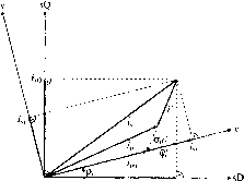 FIGURE 28.1 Direct rotor-flux-oriented vector control scheme of an induction motor with impressed stator currents, (a) Drive scheme, and (b) vector diagram. controlled drive, the stator currents must be transformed into the required special reference frame (e.g. for a stator-flux-oriented controlled drive, the stator current components in the stationary reference frame must be transformed into the stator current components in the stator-flux-oriented reference frame). It is a common feature of all vector-controlled drives that the modulus and phase angle of the ac excitation are controlled. However, since the reference frame is aligned with the selected flux hnkage space vector (e.g. stator flux linkage space vector), the transformation contains the angle of the flux linkage space vector (e.g. stator flux angle, with respect to the real axis of the stationary reference frame). Thus, the implementation of vector control requires the flux angle and also the flux linkage modulus and a major task for an implementation is to have an accurate flux linkage estimation. However, this is also a major task in a drive employing direct torque control. When the selected flux linkage is the stator flux linkage, in principle, it can be easily obtained by using terminal voltages and currents. This follows directly from physical considerations, since in the stationary reference frame, the stator flux linkage is the integral of the terminal voltage minus the ohmic stator loss, = J(Ws - RQdt (where xj/, щ and 4 are the space vectors of the stator flux hnkage, stator voltage and stator current, respectively, and they are expressed in the stationary reference frame). However, at low stator frequencies some problems arise when this technique is applied [43], since the stator voltages become very small and the ohmic voltage drops become dominant, requiring very accurate knowledge of the stator resistance and very accurate integration. The stator resistance can vary due to temperature changes; and this effect can also be considered by using a thermal model of the machine. Drifts and offsets can greatly influence the precision of integration. The overall accuracy of the estimated flux linkage vector will also depend on the accuracy of the monitored voltages and currents. At low frequencies more sophisticated techniques must be used to obtain the stator flux linkages. The monitoring of the stator voltages can be ehminated in a voltage-source inverter-fed machine, since they can be reconstructed by using the monitored value of the dc link voltage and also the switching states of the switching devices (of the inverter). As shown in Section 28.2.3.2, the components of the stator flux hnkage space vector can also be used to obtain the rotor speed signal in a speed sensorless drive, i.e. by utilizing the speed of the stator flux linkage space vector (which is equal to the rate of change of the angle of the stator flux linkage space vector). When the selected flux hnkage space vector is the rotor flux linkage vector (ф^), it is also possible to obtain it from the terminal quantities by first obtaining the stator flux linkage vector (ig), and then by applying the appropriate modifications, = (4/m)(As - s4) where and are the rotor, magnetizing and stator transient inductances respectively and 4 is the space vector of the stator currents expressed in the stationary reference frame. This follows directly from the fact that the stator and rotor flux linkage space vectors can be expressed as ф^ = LJ + Li and ф^ = + Li, where 4 is the rotor current space vector in the stationary reference frame. Thus an accurate knowledge of the machine inductances is required and this is a difficult problem, since they can vary with the saturation level, and the conventional tests (no-load and blocked rotor tests) do not give accurate values for an induction machine with closed rotor slots. Furthermore, at low frequencies the same problems arise as with the stator flux hnkage estimation, and to avoid these, various rotor flux models can be used. Some of these models also use the rotor speed (or rotor position), which can be monitored, but in sensorless applications, the speed or position is not monitored directly, but is estimated by using advanced control (observers, inteUigent systems, etc.) or other techniques. There are basically two different types of vector control techniques: direct and indirect techniques [35]. The direct implementation rehes on the direct measurement or estimation of the rotor-, stator- or magnetizing flux linkage vector amplitude and position. The indirect method uses a machine model, e.g. for rotor-flux-oriented control it utilizes the inherent slip relation. In contrast to direct methods, the indirect methods are highly dependent on machine parameters. Traditional direct vector control schemes use search coils, tapped stator windings or Hall effect sensors for flux sensing. This introduces limitations due to machine structural and thermal requirements. Many apphcations use indirect schemes, since these have relatively simpler hardware and better overall performance at low frequencies, but since these contain various machine parameters, which may vary with temperature, saturation level and frequency, various parameter adaptation schemes have been developed. These include self-tuning controller applications. Model Reference Adaptive System (MRAS) applications, applications of observers, applications of intelligent controllers (fuzzy, neuro, fuzzy-neuro controllers), etc. If incorrect modulus and angle of the flux hnkage space vector are used in a vector control scheme, then flux and torque decoupling is lost and the transient and steady-state responses are degraded. Low frequency response, speed oscillations, loss of input-output torque linearity are major consequences of detuned operation together with decreased drive efficiency. To illustrate a simple vector-controlled drive. Fig. 28.1(a) shows the schematic drive scheme of an induction motor with impressed stator currents employing direct rotor-flux-oriented control. In the drive scheme of Fig. 28.1(a), the expression of the electromagnetic torque given by Eqn. (28.3) has been used, but for simplicity, the notation has been simplified, thus с = q., 4 = 4 and hence t = qj.ij.4y Furthermore, the modulus of the rotor flux linkage space vector can be expressed as \ф^\ = Тщ! Vrl where is the magnetizing inductance of the induction machine and ijj-l is the modulus of the rotor magnetizing current space vector shown in Fig. 28.1(b). The flux-producing and torque-producing stator current references (4xref 4yref) obtained on the outputs of the flux and torque controllers respectively (which can, e.g., be PI controllers), and are then transformed to the stator currents in the stationary reference frame (isDref 4Qref) where aU the current components are also shown in Fig. 28.1(b). For this purpose 4ref = 4Dref + i4Qref = (4xref + i4yref) JPr) used, where is the position of the rotor flux linkage space vector (with respect to the real axis of the stationary reference frame). For illustration purposes Fig. 28.1(b) shows aU the stator current components and also the angle p. In the drive scheme of Fig. 28.1(a), the torque-producing stator current (4y) and the modulus of the rotor magnetizing current are obtained on the output of a rotor flux hnkage model. In the simple case shown, the rotor flux linkage model uses the monitored rotor speed and also the monitored stator currents as inputs. Such a model can be obtained by considering the rotor space vector voltage equation of the induction motor [32]. This yields the modulus and angle of the rotor flux linkage space vector (hence the name flux model), but since the rotor flux modulus is the product of and thus I ijj. I can also be obtained. Furthermore, since the position of the rotor flux linkage space vector (p) is also determined in the flux model, and since the stator currents are also inputs to the flux model (in practice only two stator currents are required), the torque-producing stator current 4y can also be obtained. For this purpose the relationship between the stator current space vector expressed in the rotor-flux-oriented reference frame (4) and the stator current space vector expressed in the stationary reference frame (4) is considered; thus 4 = 4x + i4y = 4 P(~iPr) where 4 is the space vector of the stator currents in the stationary reference frame 4 = (з)(4а + 4b + 4c)- Щ- 28.1(a), FG is a function generator, on the output of which the modulus of the rotor magnetizing current reference (limrrefl) obtained, and its input is the monitored speed. This can be used for field-weakening purposes. When the conventional field weakening technique is used, then below base speed IVrrefl constant, but above base speed it is reduced, i.e. it is inversely proportional to the rotor speed. In Fig. 28.1(a), the electromagnetic torque reference is obtained on the output of the speed controUer. This can be a conventional PI controUer, a fuzzy logic controUer, etc. It can be seen that the drive scheme shown in Fig. 28.1(a) also contains two current controUers and 4y is obtained (in the flux model) by utUizing the transformation exp(-;pj.), but the transformation ехр(;р^.) is also used (to obtain 4Dref 4Qref)- Howcvcr, it wiU be shown below that the current controllers and these transformations are eliminated when direct torque control is used. Figure 28.2 shows the schematic drive scheme of an induction motor with impressed stator currents employing indirect rotor-flux-oriented control. In Fig. 28.2(a) the torque and flux producing stator current references (4xref 4yref) the 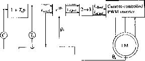 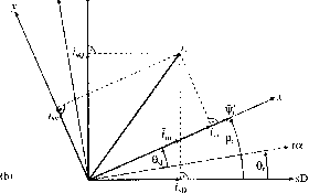 FIGURE 28.2 Indirect rotor-flux-oriented vector control scheme of induction motor with impressed stator currents, (a) Drive scheme and (b) vector diagram. angular slip frequency reference {о)\{) are generated from the reference electromagnetic torque (tj-f) and reference rotor magnetizing current modulus (hmrref D- The rotor position (6) is monitored and is added to the reference value of the slip angle (siref) to yield the position of the rotor magnetizing current space vector (or rotor flux linkage space vector). These angles are also shown in Fig. 28.2(b). The transformation of 4xref 4yref io the threc-phase stator reference currents is simUar to that shown in the direct scheme above (see Fig. 28.1(a)). The expressions used for the estimation of 4xref cOgij-gf foUow from the rotor voltage equation of the induction machine [35], and these expressions are cOgj-gf = 4yref/(r4xref) and 4xref = (1 + rP)l Wefl whcrc Tj. is the rotor time constant and p is the differential operator, p = d/dt. 28.2.1.3 Permanent Magnet Synchronous Machine and Synchronous Reluctance Machine Vector Control Inverter-fed synchronous motors are widely used in high-performance variable-speed drive systems. If the synchronous machine is supplied by a current-controUed voltage-source PWM inverter, then the stator currents are decided by the reference speed or reference electromagnetic torque and the inverter drives the synchronous motor so that the instantaneous stator currents foUow their reference values. For high- performance drives it is possible to use various rotor configurations: rotors with permanent magnets, reluctance type, and electrically excited rotors. There are basically three types of permanent magnet synchronous machines (the permanent magnets are on the rotor). In the permanent magnet synchronous machine with surface-mounted magnets, the (polar) magnets are located on the surface of the rotor and the machine behaves like a smooth-air-gap machine (the direct and quadrature-axis synchronous inductances are equal, Lj = L) and there is only magnet torque produced. In the permanent magnet synchronous machine with inset magnets, the (subpolar) magnets are inset into the rotor (directly under the rotor surface), and this is a salient-pole machine (Lj L) and both magnet torque and reluctance torque are produced. In the permanent magnet synchronous machine with buried magnets (interior magnets), the magnets are buried in the rotor (Lgj Ф Lgq) and again both magnet and reluctance torques are produced. There are basically three types of permanent magnet machines with buried magnets, depending on how the magnets are buried in the rotor: the magnets can be radially placed, axially placed or they can be inclined. A synchronous machine with reluctance rotor (SYRM) can have various rotor configurations. In earlier constructions, rotor saliency was achieved by removing certain teeth from the rotor of a conventional squirrel cage. Such synchronous reluctance machines with low output power have been used for a long time and their inferior performance, combined with their relatively high price, have resulted in their limited use. However, as a result of recent developments, more reliable and robust new constructions exist; these have basically three types of rotors: segmential, flux barrier and axially laminated rotors. In the SYRM with segmental rotor, saliency ratios (L/L) of 6-7 have been obtained. If the number of rotor segments is very large, then a distributed anisotropic structure is obtained, which is similar to the various axially laminated structures used in the past. By using multiple segmental structures, the saliency ratio can be increased. In the SYRM with axially laminated rotor, the rotor is made of conventional axial laminations bent into U or V shapes and stacked in the radial direction. With this structure it is possible to produce very high sahency ratios, and sahency ratios of 9-12 have been obtained. This also leads to fast torque responses. A synchronous reluctance machine is a salient-pole machine which produces reluctance torque. 28,2,1,3,1 Permanent Magnet Machines In a permanent magnet synchronous motor with surface-mounted magnets, torque control can be achieved very simply, since the instantaneous electromagnetic torque can be expressed similarly to that of the dc machine given by Eqn. (28.1): 4 = Cvvhc, (28.5) where Cp is a constant, ф^ is the magnet flux (rotor flux in the rotor reference frame), and 4 is the torque-producing stator current component (quadrature-axis stator current in the rotor reference frame). Both xj/ and 4 are shown in Fig. 28.3(b). Equation (28.5) can be obtained in many ways. However, according to simple physical considerations, the electromagnetic torque must be maximum when the torque angle {d) is 90°, and the torque varies with the sine of the torque angle, which is the angle between the space vector of the stator currents and the magnet flux (it is also shown in Fig. 28.3(b)). It follows from Fig. 28.3(b) that the quadrature-axis stator current is 4I sin. The expression of the torque is also similar to those shown in Eqns. (28.2)-(28.4) for the induction motor, and this is an expected physical feature. It can also be seen that the electromagnetic torque can be controlled by controlling the stator currents. The torque expression also follows directly from the fact that for all singly salient electrical machines the instantaneous electromagnetic torque can be considered to be equal to the cross vectorial product of the stator flux hnkage space vector and stator current space vector: te = Ср(Аз X 4) = Cf(Ls4 + iAf) X С = fAf >< = Apq (28.6) where the cross-vectorial product is denoted by x, and xj/ and 4 are the space vectors of the stator flux hnkage and stator current space vectors, respectively, in the rotor reference frame and Lg is the stator inductance {ф^ is the magnet flux). It can be seen that the electromagnetic torque is proportional to the magnet flux (rotor flux) and the quadrature-axis stator current (torque producing stator current). If the magnet flux is constant, and the quadrature-axis current is changed rapidly (e.g. by a current-controlled PWM inverter), a quick torque response is obtained. In contrast to the vector control scheme of the induction motor, the vector control scheme of the permanent magnet induction motor is simpler. This follows from the fact that the magnet flux is fixed to the direct axis of the rotor reference frame and the space angle between the magnet flux and the direct axis of the stator reference frame is equal to the rotor angle, which can be monitored by using a position sensor (in a sensored drive). In contrast to this, in the induction motor, e.g. if rotor-flux-oriented control is performed, it is also necessary to know the position of the rotor flux linkage space vector with respect to the direct axis of the stator reference frame, and in general this angle is not equal to the rotor angle and its determination requires the use of a flux model. In the vector control scheme for the pm synchronous motor the quadrature-axis stator current (in the rotor reference frame) can be obtained simply by considering that, when the stator current vector is expressed in the rotor reference frame, then 4 = 4 P(~ir)- this expression the rectangular form of the stator current vector in the rotor reference tWr- * controller tsBttf Current-controlled  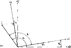 FIGURE 28.3 Rotor-oriented vector control scheme of a permanent magnet synchronous motor with surface mounted magnets supplied by a current-controlled PWM inverter, (a) Drive scheme and (b) vector diagram. frame is = 4d + i4q the stator current vector in the stator (stationary) reference frame is 4 = 4d + i4Q = I4exp(jas), where as shown in Fig. 28.3(b), is the angle of the stator current vector (with respect to the direct axis of the stationary reference frame). Thus finally 4 = 4d +i4q = 141 exp[j(as - 0J.)] is obtained, yielding 4q = \h\sm{a,-e,) = I4sin() (28.7) in agreement with that discussed above, and hence the electromagnetic torque can be expressed as Ч = fAfI4I sin(a3 - в,) = СрАр4д (28.8) It foUows that, if the stator current modulus and angle are known (e.g. by using a rectangular-to-polar conversion of the measured direct- and quadrature-axis stator current components 4d 4q) the rotor angle (0) is measured (e.g. by a suitable position sensor), then the quadrature-axis stator current can be simply determined according to Eqn. (28.7). As stated above, Eqn. (28.8) is physically expected, since it shows that the electromagnetic torque varies with the sine of the torque angle (torque angle д = - 9). It also foUows that maximum torque per stator current is obtained when the torque angle is ninety degrees. Equation (28.8) forms the basis of rotor-oriented vector control schemes, which use a position sensor. Figure 28.3(a) shows a possible implementation of a vector-controUed (rotor-oriented controUed) permanent magnet synchronous machine with surface mounted magnets, where the machine is supplied by a current-controUed PWM inverter. In Fig. 28.3(a) the electromagnetic torque reference (tgj.gf) is proportional to 4qref siucc tgj.gf = cip4qref- Bclow basc speed, 4dref = 0 since in this case the torque angle is 90° and maximum torque/ampere is obtained. Fiowever, above base speed, in the field-weakening range, where the inverter voltage limit is reached, a negative value of 4dref this case the torqiie angle is larger than 90°. Since the stator current modulus 4I cannot exceed its maximum value (4max) thus 141 = VCsd + sq) - 4max the quadrature-axis stator current 4q may have to be reduced, thus tj-ef may also have to be limited. The stator current components in the stationary reference frame (4Dref 4Qref) obtained by using the transformation exp( jO), and this is foUowed by the application of the two-phase-to-three-phase transformation. This scheme is similar to that shown in Fig. 28.2(a). Fiowever, for the permanent magnet synchronous motor, in Fig. 28.3(a) the rotor position (0J.) is used (rotor-oriented control) instead of the position (p.) of the rotor flux hnkage space vector (rotor-flux-oriented control) and the angular shp frequency reference is zero. Furthermore below base speed, 4dref = It is also possible to have a speed-sensorless implementation, where the rotor speed is obtained by utUizing the speed of the stator flux hnkage space vector (rate of change of the angle of the stator flux hnkage space vector). Although such a drive can be used in a wide speed range, it wiU not give fully controUed torque operation down to zero speed. One main difference between the vector control of a synchronous machine and the vector control of an induction machine is their cross-magnetizing behavior. In an electrically excited synchronous machine, the stator currents produce a rotor flux which is in space quadrature to the flux produced by the field winding. Thus, simUar to the cross-magnetizing armature reaction of a dc machine, a reduction of the field flux can be caused at high values of torque. In a synchronous machine with surface mounted magnets, normally this demagnetization effect is smaU, due to the large air-gap associated with the magnets, but at high currents it can cause magnet demagnetization. This effect must be considered when designing the motor. Fiowever, in an induction machine subjected to vector control (e.g. rotor-flux-oriented control), the quadrature-axis rotor flux linkage (in the rotor-flux-oriented reference frame) is zero. Thus there is no demagnetization effect caused by the torque producing stator current. The 4d = 0 control method has been a popular technique for a long time and has been used to avoid the demagnetization of the magnet material. In general, in a permanent magnet synchronous motor, where the direct- and quadrature-axis stator inductances (Lj, L) are not equal, e.g. for a machine with interior magnets, independent control of 4j (flux-producing current) and 4 (torque-producing current) is possible by considering that the direct-axis stator flux linkage is i/gj = Ке(Дз) = <Af + sd4d (see also the definition used in Eqn. (28.6) and the expression of the electromagnetic torque is te = c[iF4q + (kd - kq)hdhql This last cquatiou follows from the fact that, in general, t = сф x 4 holds, where Al = Asd +iAsq Asd = Af + 4d4d Asq = 4q4q- 28,2,1,3,2 Synchronous Reluctance Machines Due to the low cost, simplicity of control, absence of rotor losses and field-weakening capability, recently increased research efforts has focused at varioius industrial and automotive applications of synchronous reluctance motors. The synchronous reluctance motor (SYRM) is a greatly robust singly sahent machine (similar to the stator of an induction machine, the stator bore is smooth but slotted and there is a symmetrical three-phase stator winding carrying balanced three-phase currents; however, there is a salient-pole rotor). In a high-performance synchronous reluctance motor the rotor is axially laminated; this results in high saliency ratios (high Tgd/sq where Lj and are the direct- and quadrature-axis synchronous inductances, respectively). The high saliency ratio results in high power density, increased torque, high power factor and increased efficiency. Reluctance torque is created by the ahgnment of the minimum reluctance path of the rotor with the rotating magnetizing mmf which is produced by the stator currents (there are no rotor currents in a cageless design). The electromagnetic torque of a SYRM can also be expressed similarly to that of the induction motor or permanent magnet synchronous motor. In general, the electromagnetic torque is developed by the interaction of the stator flux linkage space vector and stator current space vector, thus = fPi/s X 4 5 where P is the number of pole pairs and the stator flux linkage and current space vectors in the rotor reference frame are = ф^ + ]ф^ and 4 = 4d + Jhq respectively. The subscripts d and q denote the direct- and quadrature-axis quantities, respectively, in the rotor (synchronous) reference frame. Due to the absence of rotor currents, the stator flux linkages are established by the stator currents, thus Asd = kdhdy and ф^ = L3q4q, where L and L are the direct-and quadrature-axis synchronous inductances, respectively. It follows that
 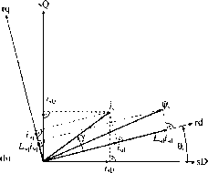 FIGURE 28.4 Rotor-oriented vector control scheme of a synchronous reluctance motor supplied by a current-controlled PWM inverter, (a) Drive scheme and (b) vector diagram. where 9 is the rotor angle, and this is why in general, the rotor position is required (e.g. in a control scheme using rotor-oriented control) for the transformation of the measured stator currents (4d 4q)- better understanding. Fig. 28.4(b) shows the stator current vector, the stator flux linkage vector and also the various reference frames. Equations (28.9) and (28.10) can be used for the implementation of the rotor-oriented control of the synchronous reluctance motor. However, Eqn. (28.9) can also be arranged into the following form, if ф^ = Tsd4d utilized: te = inkd - kq)hdhq = ЦП sq/sd)]Asd4q = Asdq (28.11) 4 = f Al X i = I Asdq - Asdd) = (4d - 4q)4d4q- (28.9) It is important to note that in Eqn. (28.9) the stator current components (i, 4q) expressed in the rotor reference frame, and can be obtained from the stator currents in the stationary reference (4d5 4q) where с = P(1 - Т^/Т^) and it should be noted that in general it is saturation dependent. Equation (28.11) resembles the torque expression of a separately excited dc motor, to that of a vector-controlled induction motor and also to that of a permanent magnet synchronous motor with surface magnets; see Eqns. (28.1), (28.2), (28.3) and (28.5). In a vector-controlled synchronous reluctance motor drive, where the motor is supphed by a current-controlled PWM inverter, and where rotor-oriented control is performed, independent control of the torque and flux (torque-producing stator 1 ... 71 72 73 74 75 76 77 ... 91 |
|
© 2026 AutoElektrix.ru
Частичное копирование материалов разрешено при условии активной ссылки |