 |
 |
 |
| Главная Журналы Популярное Audi - почему их так назвали? Как появилась марка Bmw? Откуда появился Lexus? Достижения и устремления Mercedes-Benz Первые модели Chevrolet Электромобиль Nissan Leaf |
Главная » Журналы » Metal oxide semiconductor 1 ... 73 74 75 76 77 78 79 ... 91 Induction motor Ger A(x) A(x) Speed tuning signal Speed estimator Speed tuning signal using space vector notation: = lm(>-*) FIGURE 28.10 Adaptive speed observer (speed adaptive flux observer) in an induction motor drive. error speed-tuning signal, which can be put into a very compact, simple form when the space vector notation is used: e = \m{}j/\e% where = \j/ jxj/and e = sD +isQ- The estimated speed is obtained from the speed-tuning signal by using a PI controller [35], thus: = pCArqsD - Ardsq) + i (ArqsD Ardsq) (28.44) where and K- are proportional and integral gain constants respectively e, = i, - i, and е, = 4q - 4q are the direct and quadrature axis stator current errors, respectively. In summary it can be seen that an adaptive observer can be used to obtain the rotor flux estimates (ij/, ird) the rotor speed is estimated by using the estimated rotor flux hnkages and using the stator current errors (е^, sq)- This is why the precise name of this speed observer is speed adaptive flux observer . The rigorous proof can be obtained by using Lyapunovs stability theory or by applying Popovs hiper-stability theorem [35]. If the chosen PI constants and are large, then the convergence of the rotor speed estimation wiU be fast. Fiowever, in a PWM inverter-fed induction machine, the estimated speed will be rich in higher harmonics, due to the PWM inverter. Thus the PI gains must be limited when the stator voltages and currents are obtained asynchronously with the PWM pattern. To ensure stability (at aU speeds), the conventional procedure is to select observer poles which are proportional to the motor poles (the proportionality factor is k). This makes the observer dynamically faster than the induction machine. Fiowever, to make the sensitivity to noise small, the proportionality constant is usually smaU. The scheme can give accurate results above 1-2 Fiz. Fiowever, in a discrete implementation of the speed observer, for smaU sampling time and low speed, accurate computation is required; otherwise, due to computational errors, stability problems can occur (roots are close to the stability hmit). For this purpose, another pole placement procedure could be used, which ensures that the low speed roots are moved away from the stability limit [35]. For DSP implementation the discretized form of the observer and the adaptation mechanism have to be used. Thus the discretized observer is described by x(k-\- 1) = Ax(k)-\-Bu(k)-\-G[i)-X(k)l where is the discretized observer gain matrix, Aj = exp(AT) /4 -h AT -h (AT)/2 is the discretized system matrix, where T is the sampling time, and = J [ехр(АТ)]Б^т ВТ + ABT/2. The speed observer discussed above will only give correct speed estimates if correct machine parameters are used in the system matrix and in the input matrix. Fiowever, these also contain the stator and rotor transient time constants, T and Т/, which also vary with temperature (since they depend on the temperature-dependent stator and rotor resistances, respectively. The variation of the stator resistance has significant influence on the estimated speed, especially at low speeds. On the other hand, in a high dynamic performance induction motor drive, where the rotor flux is constant, the influence of the rotor resistance variation is constant, independent of the speed, since the speed estimation error and the rotor resistance error cannot be separated from the stator variables. The influence of the stator resistance variation on the speed estimation can be removed by using an adaptive stator resistance estimation scheme [35] and in this case, a drive using this scheme can be operated in a stable manner in a very wide speed range, including extremely low speeds as weU. Fiowever, it should be noted that the speed observer discussed above uses the monitored stator voltages. In a PWM inverter-fed induction machine the stator voltages contain harmonics due to the inverter and also the degree of voltage measurement deteriorates at low speeds. These problems can be overcome in various ways, e.g. by reconstructing the stator voltages from the inverter switching states by using the monitored dc link voltage (see above). Alternatively, in a drive system, instead of the measured stator voltages it is also possible to use the reference voltages, e.g. these are the inputs to a space-vector PWM modulator. If this technique is used for the induction machine, to obtain high accuracy, it is necessary to compensate for the error between the reference and actual stator voltages by the estimation of the voltage error. For this purpose the adaptive observer shown in Fig. 28.10 must be complemented by a voltage error estimator block. This voltage error contains both a dc and an ac component, corresponding to a constant bias error between the real and reference voltage and also to an amplitude error. These errors are present due to the dead time which is required to prevent the short circuits of the inverter arms, errors caused by A/D quantization, voltage drops of the switching devices, etc. The modified observer with stator voltage error compensator is simple to implement and significantly improves the system behavior. The extra parts of this observer scheme contain a stator vohage error estimator. It can be shown by simple considerations that this voltage error estimator outputs the integral of G(4 - 4) and this signal is manipulated into other signals which are then added to the reference voltages to obtain the correct stator voltages. MRAS-Based Flux and Speed Estimation in Vector and DTC Drives For an induction machine, the open-loop speed and flux linkage estimators discussed above have utilized the stator and rotor voltage equations of the induction machine. However, the accuracy of these open-loop observers depends strongly on the machine parameters. In closed-loop estimators the accuracy can be increased. For induction motor drives five rotor speed observers using Model Reference Adaptive System (MRAS) have been described in [35]: the first four schemes are mathematical-model-based schemes, but the fifth scheme is an artificial-intelligence-assisted MRAS scheme. In a mathematical-model-based model reference adaptive system, two estimators are used. One of these is the so-called reference model, which does not include the rotor speed and the other is the so-called adjustable model, which contains the rotor speed. The outputs of the two estimators are then compared, and the error is used to obtain the adaptation mechanism (adaptation model, e.g. expression of the estimated speed). In general, in a MRAS system, some state variables, Xj, (e.g. rotor flux linkage components, ф,, ф,, or back emf components, e, e, etc.) of the machine (which are obtained by using measured quantities, e.g. stator voltages and currents) are estimated in a reference model and are then compared with state variables ij, x estimated by using an adaptive model. The difference between these state variables is then used in an adaptation mechanism, which outputs the estimated value of the rotor speed (coj and adjusts the adaptive model until satisfactory performance is obtained. Such a scheme is shown in Fig. 28.11(a) for an induction machine, where the compact space vector notation is used. However, Fig. 28.11(b) corresponds to an actual implementation, and here the components of the space vectors are shown. The appropriate adaptation mechanism (expression of the estimated rotor speed) can be derived, e.g. by using Popovs criterion of hyperstability. This results in a stable and quick response system, where the differences between the state variables of the reference model and adaptive model (state errors) are manipulated into a speed-tuning signal (г), which is then an input into a PI-type of controller (shown in Fig. 28.11(c)), which outputs the estimated rotor speed. Four mathematical-model-based schemes have been discussed in [35]: these use the speed-tuning signals 8 = 1т(ф[ф^), = Im(ee*), вд = Im(Aei*) and вд/ = Im(Api*), respectively. In these expressions ф[ and 4 denote the rotor flux linkage and stator current space vectors, respectively, in the stationary reference frame, e denotes the back emf space vector also in the stationary reference frame e = (L/L,)dф[/dt and finally the error back emf space vector is defined as Ae = e - e. The symbol denotes the quantities estimated by the adaptive model. To improve the performance of the observers described, pure integrators are not used in these schemes. Scheme 3 is robust to stator resistance and rotor resistance variations, and can even be used at very low speeds, e.g. 0.3 Hz (but not zero speed). All the MRAS observers use monitored stator currents and stator voltages (or reconstructed voltages). However, an artificial-intelhgence-based MRAS speed estimator seems to offer the most satisfactory performance, even at very low speeds (see also Chapter 29). Reference model Adaptive model Adaptation mechanism 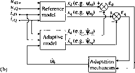 v = [ea,e/ (C) *
FIGURE 28.11 MRAS-based speed estimator scheme, (a) Basic scheme (using space vector notation), (b) basic scheme (using space vector components), (c) adaptation mechanism, (d) equivalent non-linear feedback system. Estimators Using Saliency Effects In general, in induction motor drives it is possible to estimate the rotor speed, rotor position and various flux linkages of a squirrel-cage induction motor by utilizing different types of saliency effects (rotor slotting, inherent air-gap asymmetry, intentional rotor magnetic saliency created by spatial modulation of rotor slot leakage inductance and other saliency effects, e.g. saliency created by saturation). These techniques are discussed below. Estimators using rotor slot harmonics The rotor speed and shp frequency of a cage induction motor can also be estimated by utilizing rotor slot harmonics or eccentricity harmonics. Namely, due to slotting (slot openings), there are slot harmonics produced by the variation of the reluctance due to stator and rotor slots. The rotor slot harmonics cause stator voltage and current harmonics, which can be filtered to obtain the rotor speed signal. In a speed-sensorless high-performance drive, up to now, due to the measurement bandwidth limitation, such an estimator has not been directly used for rotor speed estimation, but it has only been used indirectly to help the tuning of MRAS speed estimators. However, it is possible to use this technique for low-performance apphcations. It is a major advantage of this technique that variations in the motor parameters do not influence the accuracy of the estimation and the technique can also be used for aU loads. The rotor slot harmonics can be detected by using various techniques: utihzing monitored stator voltages or by utilizing monitored stator currents. It should be noted that the technique cannot be used at zero speed, since the slot-harmonic voltages are very smaU. Using Monitored Stator Voltages When stator voltages are monitored the foUowing physical picture is utihzed. Since the air-gap mmf contains slot harmonics, slot harmonic voltages are induced in the stator windings when the rotor rotates. Both the amplitude and frequency of these depend on the rotor speed. However, it is difficult to extract information on the rotor speed from the magnitude, because it depends not only on the rotor speed but also on the magnitude of the flux level and the loading conditions. Thus the rotor speed and the slip frequency is obtained from the frequency of these slot harmonic voltages. In a stator phase of an induction machine the magnitude of the induced slot harmonic voltages is smaU and thus to separate these from the dominating fundamental voltage, the stator phase voltages are added. Thus the resulting voltage, Щ = Ща + + ill contain a slot harmonic component Wgh, due to the fundamental mmf wave, but due to main flux saturation it wiU also contain a third harmonic component Ws3. Furthermore, when an inverter supplies the induction machine, the stator voltage (щ), wiU also contain extra time harmonic voltages, Wgj, where к is the time harmonic order. Hence in general u = -h -h Wshfc- The frequency of the slot harmonic voltage components (щ^, щ^) is related to the stator frequency and rotor speed (and the number of rotor slots, which is assumed to be known). If the mmf distribution is assumed to be sinusoidal, then the resulting stator voltage = 4a + Чв + Чс ill contain the rotor slot harmonic voltages (Wgh) and the frequency of their dominant component (fundamental slot harmonic frequency) is f = NJ =b /i = 3Nfi - Nji where = 3N ib 1. In this expression f is the rotational frequency of the rotor, f = ojjln, where ш^. is the angular rotor speed. Furthermore, f is the stator frequency (f = Ш1/2Я, where is the angular stator frequency) and is the slip frequency, f=f-f = (ш^ - ш^.)/2я = a)i/2n, where coi is the angular slip frequency and N. is the number of rotor slots per pole-pair (N. = ZJP) (Zj. is the number of rotor slots and P is the number of pole pairs). It foUows that the rotor slot harmonic frequency only depends on f, f and Nj.. By considering co = C0i(l - s), where 5 is the slip, it is also possible to express as = [2(1 - When the induction machine is supplied by a three-phase inverter, in general, the output currents and voltages of the inverter contain time harmonics (Щ], i]J. Since in the output voltage of the three-phase inverter, there are no harmonic voltages with harmonic orders 3 k, where к = 1,2,..., the voltage (щ) which is obtained by adding the three stator phase voltages (д, щ^, щ^) does not contain time harmonics if the induction motor is symmetrical. However, slot harmonic voltages are present in the stator winding, due to the time harmonic fluxes produced by the time harmonic currents. The slot harmonic frequency due to the /cth time harmonic can be expressed as /shfc - NJ, ± kf = 3Nf ± 6mf - N/31 k = 6m-l NJ ± kf = 3Nf ± 6mf - NJ, k = 6ml where N, = 3N-\-l, m = 1, 2,.... If saturation of the main flux paths occurs, a third-harmonic voltage (щ) is produced in each stator phase voltage. These third harmonic voltages are in phase with each other and therefore are present in the sum of the phase voltages. In general the magnitude of the third-harmonic voltage in a stator phase is smaUer than the magnitude of the fundamental voltage in the corresponding stator phase, but the slot harmonic voltage is also smaU and thus щ cannot be ignored even if the motor operates at rated voltage. The third harmonic voltage is approximately one fifth of the slot harmonic component. If an induction motor with star-connected stator windings is assumed with the neutral point accessible, then the summation of the stator voltages can be performed by using three potential transformers, whose secondary winding are connected in series. It is also possible to use operational amplifiers to add the three stator voltages, but in a DSP controUed drive the addition can be simply done numerically. Thus Щ is obtained. It foUows from above, that u, can be obtained by removing the voltage components and щ^. This can be achieved by using various circuits [34, 35] and then the frequency of the rotor slot harmonic (f) can be obtained from щ^. By subtracting the stator frequency, fsh- fl = N,f is obtained and muhiphcation of this by 2n/N, gives the angular rotor speed со, = 2n(f - f)/N,. The shp frequency can be obtained by using / = f - f, where f = CD,/2n. However, special considerations are required in the low-speed range, because at low speeds the amplitude of the slot harmonic voltages decrease. Using Monitored Stator Currents By utihzing rotor slot harmonics, the rotor speed can also be estimated by using the monitored stator line currents and performing harmonic spectral estimation. This is the preferred technique, since in speed-sensorless drives there is always the need for current monitoring, and it is useful to reduce the number of sensors required (by eliminating the voltage sensors). The stator current slot harmonics can be similarly obtained as given above: thus, if a stator line current of a PWM inverter-fed induction motor is monitored, then 4, = N,f ± kf holds, where f = f(l - s). For the purpose of speed estimation, in a PWM inverter-fed induction motor drive, a hne current is monitored, scaled and low-pass filtered (to eliminate high frequency PWM harmonics) and, e.g., digital FFT can be used to detect the speed dependent rotor slot harmonic (4). When is known, by using the expression given above for the fundamental slot harmonic frequency, the angular rotor speed can be obtained as CO, = 2nf = 2n( f±f)/N,. It follows that the accuracy of the estimated rotor speed depends on the accuracy of the measurement of f and f. Estimators using eccentricity In practice, the air-gap mmf also contains space harmonics due to various types of asymmetries, e.g. eccentricity [35], by neglecting the effects of magnetic saturation, and assuming sinusoidally distributed stator windings, the stator current contain harmonics with the frequencies / = [(cZ2 ± n)(l - s)/P ± k]f, where f is the fundamental stator frequency, с is any integer, z2 is the number of rotor slots, and /7j is the eccentricity order number, which for static eccentricity is zero and for dynamic eccentricity is 1. Furthermore, 5 is the slip, P is the number of pole pairs and к is the order of the time harmonics {k = 1, 3, 5, 7, etc.). It should be noted that, if с = 1, and k = 1 and n = 0, the expression reduces to that given above for the dominant slot harmonic frequency. It also follows that for pure dynamic eccentricity (c = 0, /7j = l, /c=l), the current harmonics due to eccentricity are / = [1 lb (1 - s)/P] f and this expression is independent of z2 and only requires knowledge on the pole-pair number, which can however be obtained by simple measurement. Thus if the pole-pair number is known, and in an initial test the harmonics associated with pure dynamic eccentricity are first detected by FFT from the measured stator current, then it is possible to estimate the slip (and also the speed). Although the harmonics caused by pure eccentricity enable z2-independent speed and slip estimation, they provide much lower slip resolution than the slot harmonics for a given samphng time. Thus the slot harmonics can be used to provide the accurate speed estimation and the eccentricity harmonics are only used to give extra information for initialization of the slot harmonic estimator. By using the estimated shp and also the expression of the eccentricity harmonics given above, it is then possible to use a search algorithm to obtain z2, n and к from a table containing possible values of these parameters. When these are known, these parameters can be used in a speed-sensorless induction motor drive using current harmonic spectral estimation. However, this technique cannot be used at zero speed. Estimation using other techniques which are suitable for low-frequency operation General It is possible to estimate flux linkage space vector position (and using this information, the rotor position) by using flux hnkage detection based upon saturation induced inductance variations, where test voltages are applied to the stator terminals of the machine and the flux linkage space vector position is detected from measured current responses. Furthermore, in the presence of injected high frequency stator voltages, for the estimation of flux linkage space vector position and the rotor position, it is also possible to use saliency effects, which are due to magnetic saturation (main flux or leakage flux saturation) or saliency effects intentionally created by using special rotor construction, where spatial modulation of the rotor leakage inductance is created (e.g. by periodically varying the rotor slot opening widths or by varying the depths of the rotor slot openings, etc.). In addition, it is also possible to extract the rotor position by using the fact that, in a cage induction motor, the motor leakage inductance varies with the rotor position. Some of these techniques are discussed briefly below. When an induction motor operates at extremely low frequency, the signal-to-noise ratio of the stator vohage measurement is very poor and the stator ohmic drop is dominant (see also the discussion above on open-loop estimators). Thus it is difficult to obtain an accurate value of the stator (or rotor) flux linkages and the rotor speed by any of the mathematical-model-based speed estimators discussed above. When the conventional mathematical model of the induction machine is used, at zero stator frequency the machine fluxes and the rotor speed are not observable, since in essence the induction motor behaves like a resistance (stator resistance). However, various types of anisotropics (saliency due to saturation, rotor slotting, etc) can be utihzed in smooth-air-gap machines for flux, speed and position estimation. For this purpose several techniques exist, but it is a common feature of most of these that they also use injection schemes (voltage or current injection). These allow low-speed operation, but for high-speed operation other schemes must be used. Furthermore, so far, for smooth-air-gap induction machines with closed rotor slots (e.g. for many low- and medium-power induction motors) these techniques have not given satisfactory solutions. This is mainly due to the fact that these algorithms rely on the variation of the rotor leakage inductance with the level of the main flux (there is main flux saturation dependency), but in motors with closed rotor slots, there is also saturation of the leakage fluxes. However, there is one type of algorithm, which can be effectively used even at very low stator (and also zero) stator frequency, but instead of relying on saturation effects, it utihzes the position dependency of the leakage inductance (transient inductance) of a squirrel-cage induction motor. This technique requires voltage sensors and also some modifications to the conventional PWM technique used (see Section 5.3.2). Estimation Utihzing Saturation Induced Saliencies Various techniques are described below which utilize saturation induced sahencies. These can be used to obtain the rotor position, rotor speed, flux position, etc. Estimation using the INFORM technique A simple technique is described below which in principle can be used for the rotor position estimation of permanent magnet synchronous machines and also synchronous reluctance machines [27, 35, 36]. This technique (the INFORM method) can be well used for motors where there is physical saliency (e.g. permanent magnet motor with interior magnets). This is based on the fact that, in the induction motor, due to saturation of the stator and rotor teeth, the stator inductances depend not only on the level of saturation but also on the position of the main flux. It follows from the stator voltage equation of the saturated induction machine that at StandstiU the rate of change of the stator currents can be approximated as di/dt = щ/L. In this equation L is the complex stator transient inductance of the induction machine, whose magnitude and angle depend on the magnetic operating point and the direction of the magnetizing flux linkage space vector. By applying appropriate stator voltage test vectors {щ), the rate of change of the stator current space vector (diJdt) can be measured. The angle of the magnetizing flux linkage space vector can then be obtained since the locus of the modulus of the complex transient inductance is an eUipse and the minimum of this eUipse is in the direction of the magnetizing flux linkage space vector. The INFORM technique has to be complemented by a Kalman filter or another state observer and needs the use of other sensorless techniques for higher speeds. Estimation using high-frequency magnetic saliency It is also possible to estimate flux linkage space vector position in an induction machine by tracking of high-frequency magnetic saliency created by magnetic saturation (main flux or leakage flux saturation) at zero or low rotor speeds [3, 16, 35]. For this purpose high-frequency voltages or currents are injected in the stator of the induction machine. In a VSI-fed drive, the injected voltages can also be produced by the PWM VSI used in the drive scheme (thus no extra injection circuit is required). It wiU be shown below that this technique is only possible in a saturated smooth air-gap machine, due to the physically existing cross-saturation effect (which effect is due to the saliency caused by saturation). It is weU known [33] that, as a consequence of magnetic saturation, saliency is created and the stator direct and quadrature axis inductances become asymmetrical (Т^ 7 Lq) and also coupling wiU exist between the two axes (cross-saturation effect, Lj)q 7 0). It has been shown [33] that, due to saturation, aU the inductances are functions of the saliency position (), and = Tl + ALcos(2), Lq = LiALcos(2), Lq = Lqj) = ALsin(2). It then foUows that, due to saturation, the stator transient inductances in the direct and quadrature axis (of the stationary reference frame) are also asymmetrical. The direct and quadrature axis stator transient inductances (Lp, Lq) and also the cross-couphng transient inductances (Lq = Lq) are functions of the angle ju, and Lp = L[ -h AV cos(2), Lq = Ll - AL cos(2), L[)q = = AL sin(2), where L = (4d + sq)/2 and AL = (Ld - L)/2, In these expressions L and are the direct and quadrature axis transient stator inductances in the direct and quadrature axes of the existing saliency, respectively. As expected, the cross-saturation couphng and inductance asymmetry disappear when When high-frequency stator voltages are injected into the stator windings the measured stator currents can be used to obtain information on the position of the saliency. For high stator frequencies, the stator equations of the saturated induction machine in the stationary reference frame can be weU approximated by the voltages across the appropriate stator transient inductances. Thus when a symmetrical three-phase high-frequency stator voltage system with amplitude (7, angular frequency щ {щ is high), is injected into the stator, in the steady state, the stator currents wiU be displaced from the stator voltages by 90° (since the stator transient inductances are dominant), and it foUows from the stator voltage equations (in the stationary reference frame), that the space vector of the stator currents in the stationary reference frame can be expressed as 4 = P( iiO + hn P[ Kl ~ iOl-This current response can be measured. It can be seen that the first term in the current response is independent of the angle fi; thus, in practice the second term can be used to estimate fi (which is the saliency position). For completeness it should be noted that the amplitudes of the two current components are 4o = (siMK;/af-АГ) and I, = {UJcoL/ (Lf - L). It foUows that in the absence of cross-saturation (no sahency) AL = 0 and it is not possible to estimate the second term in the expression of the currents (since / = 0). Furthermore, the first term is a direct measure of the saliency present: it characterizes the average stator transient indue- tance. By resolving the stator current space vector (4) into its real and imaginary axis components, and iQ are obtained. The angle /л, which is present in the stator current components, can then be extracted in a number of ways. One possibility is to use a demodulation scheme involving heterodyning [16], where the direct axis stator current (4Di) is multiplied by sin(2/i - cot), and the quadrature axis stator current (4Qi) is multiplied by cos(2/i - cot), where jl is the estimated saliency angle (in electrical radians) and then the difference of these two signals is obtained: s = 4Qi cos(2/i - cOjt) - 4DiSin(2/i - cOjt), where s is the position error signal. When the expressions of the direct and quadrature axis stator currents are substituted into this expression, then the newly obtained expression becomes г = sin[2(a;it - jl)] + /gii sin[2( - jl)]. The second term of this contains the spatial position information and approaches zero as jl fi (where jl is the estimated and fi is the actual saliency position). The first term can be removed by a low-pass filter. The remaining second part (heterodyned and filtered signal, Sf) is in the form of a linear position error (as fi fi), Sf = /gii sin[2( - fi)] 2Ii(fi - jl). This signal can then be used to drive a controller, described by -\- K2/P, where and K2 are gains of the controller. It follows that the saliency position is obtained as /i = j cbdt, where cb = (K -\- Хз/р)- By using the saliency position, it is also possible to obtain estimates of the rotor flux hnkages. For this purpose a flux model can be used, thus the measured stator current components of the induction machine are first transformed into the reference frame rotating with the saliency, by using the transformation exp(-j/i), and the obtained transformed stator currents are then used as inputs into the flux model of the machine. The obtained flux linkage components canthen be transformed into their stationary axis components (ij/,, Фщ) by using the transformation exp(jjl). It should be noted that, so far, experimental proof of this saturation-induced saliency technique has not been given for induction motors. The best machine configurations for saturation-induced saliency tracking are those with open or semi-closed rotor slots and are designed so that main flux saturation has a much greater impact on the stator transient inductance than locahzed leakage saturation. It is important to note that robust tracking of saturation induced sahency may require operation at flux levels which are considerably higher than normal or rated. The maximum operational speed is then limited by core loss and/or stator voltage. Field-weakening greatly beyond base speed may then be not possible. Another technique has been described recently [4, 36], which allows sensorless vector control at zero flux frequency. With this scheme it is possible to hold a load stationary for a long time, even at zero frequency. For this purpose, saturation effects are again utilized to obtain the position of the rotor flux linkage space vector. However, in this scheme both the stator voltages and currents have to be measured. For estimation purposes a special test current space vector (A4) is added to the reference stator current space vector (4ref) where the test current space vector is pulsating in parallel with the direction of the estimated rotor flux vector axis. It is a very important feature of the scheme that, due to magnetic saturation, the rotor current space vector produced by the test stator current space vector (-A4) is displaced by an angle (7) with respect to the test current space vector. This follows from the fact that, by assuming fast and small variations of the stator currents, it can be shown that Ai, = Ai,-\-jAi,y where Ai, = -[1/(1 + Lri/b)]A4. = iA4. and A4 = -[1/(1 + LJ Lj)]A4 = 24 where ki and are saturation dependent gains, L,i is the rotor leakage inductance, and L and L are the dynamic and static inductances, respectively (L is the tangent slope and L is the static (chord) slope of the magnetising curve). Under saturated conditions L < L, and thus k2 > k, and therefore the test motion of the stator current space vector (A4) is transferred into the motion of the rotor current space vector without any delay and the current transfer in the x axis (axis coaxial with the rotor flux linkage space vector) takes place with smaller gain than the current transfer in the у axis (axis in space quadrature to rotor flux hnkage space vector). In other words, under saturated conditions the space vector -A4 is displaced from the space vector A4 by the shifting angle 7. In a saturated machine, it is this effect which causes the shifting angle 7 to be different from zero when the estimated rotor flux position (p,) is different from the actual rotor flux position (pJ, i.e. when the error angle is S = p, - p, Ф 0. It is the angle 7 which is used to obtain the position of the rotor flux linkage space vector. It is important to note that, if p, = p, {S = 0) then 7 = 0 and, when the shifting angle is not zero, in general it has an opposite direction to the error angle. It follows from the above that, to obtain the shifting angle, the negative rotor current components -Ai,, -A4 due to the test stator current space vector have also to be known in the estimated-rotor-flux-oriented reference frame. Another high-frequency injection technique was presented recently [14], where, for the purpose of sensorless rotor flux estimation, a high-frequency signal is injected in the stator of an induction motor. However, this signal is not a rotating signal, but a signal which fluctuates at a synchronous frequency with the fundamental stator frequency. The difference between the direct axis (flux axis) and quadrature axis terminal impedances is used for estimation of the angle of the rotor flux linkage space vector. This difference is small only at fundamental stator frequency, but becomes larger when a high-frequency signal is injected in the stator. The technique makes use of saturation and skin effects. Since the injection signal is independent of the stator frequency, the scheme can work even at very low frequency, but there is a strong dependence on the machine design. When this is also considered, the drive can work with all loads. However, at higher speeds, another sensorless scheme must be used. Another injection scheme was used in an EKF-based sensorless indue- tion motor drive [25], but no experiment results have been shown. Estimation utilizing saliency introduced by special rotor construction For the estimation of the rotor position and rotor speed, even at zero and low speeds, it is also possible to use saliency effects, which are intentionally created in an induction motor by using special rotor cage construction, where spatial modulation of the rotor leakage inductance is created. This can be achieved, e.g., by periodically varying the rotor slot opening widths or by varying the depths of the rotor slot openings, etc. In the first case, when the widths of the rotor slot openings are varied, the physical picture is simple: the wider slot openings produce flux paths of high magnetic reluctance, and thus locally low inductance, but the narrow slot openings create low reluctance flux paths and high local inductance. Although it would appear that fully closed or semi-closed rotor slot bridges could increase the amplitude of the reluctance variation, however, it is not useful to extend the spatial modulation depth to these type of slot bridges, since they would magnetically saturate and such saturation would introduce a field dependent variation of the local inductance (but the goal is to have a rotor position dependent inductance variation). It is also possible to create saliency in a cage rotor by having identical rotor slot geometry, but where the height of the conductors in the slot openings is different. The saliency-based estimation technique resembles the one described in the previous subsection, but the main difference is that in the present case there exists a deliberately introduced saliency due to physical asymmetry, whilst in the previous subsection magnetic saliency existed due to saturation. It should, however, be noted that the introduced rotor saliency is symmetric about each pole, i.e. it is ninety mechanical degrees for a four-pole machine. In order to be able to track the sahency, similarly to that discussed in the previous subsection, symmetrical three-phase high-frequency voltages are injected into the stator, (the amplitude and angular frequency of these are U and ш^, respectively). It is shown below that when special (asymmetrical) rotor constructions are used, the stator transient inductances due to asymmetry are position dependent. It is this position dependency of the inductances which causes position-dependent current responses, when the stator is supplied by high-frequency voltages. By measuring these stator currents, it is then possible to extract the information on the rotor position. When high-frequency stator vohages are injected into the stator of the induction machine, it foUows from the stator voltage equation of the induction machine in the stationary reference frame that dij/Jdt, where the stator flux linkage component is mainly a leakage flux component. This contains the appropriate stator transient inductances (sum of stator and rotor leakage inductances). It foUows that the stator currents due to the injected stator voltages can be formally expressed in the same way as for the previous scheme. Thus thecurrent response to the injected stator voltages is obtained as 4i = /gio P( iiO + 4ii P[ i(2r ~ iOl which contains a positive-sequence and a negative-sequence stator current component, where I, = (UJcdO(L,i + L[)/[(L,i + L[f -AV] and 4i = (UJco)AL/[(Li -h L[f - AL% Mathematically, the expression for 4 given above foUows directly from the analytical solution of the voltage differential equations. The positive-sequence component rotates at the speed of the injected angular frequency, the negative-sequence component rotates at a speed 2со. - co and the locus of the space vector current 4i is an eUipse. This current can be obtained from the measured stator currents by using a bandpass filter (BPF). Although 4i contains the rotor position (the angular inchna-tion of the eUipse is equal to the rotor position angle), it is difficult to extract it directly from 4i- However, the second component of the stator current contains the rotor angle, and this can be used to estimate the rotor position, by using the same technique as discussed in the previous subsection. It foUows that, by using bandpass filtering, 4i = 4Di + i4Qi is obtained, and by using the direct and quadrature axis currents (4оц 4Qi) the angular position error signal s = (4Qi)cos(20j. - cOjt) - (4Di)sin(20j. - cOjt) is first obtained which can be expressed as 8 = IQsm[2(cot - 9,)]-\-/gii sm[2(e, - 9,)]. The second term contains the rotor position information, and approaches zero as 9, 9, (where 9, is the estimated and 9, is the actual rotor position). The first term can be removed by a low-pass filter. The remaining second part (heterodyned and filtered signal) is in the form of a linear position error (as 9. 9.); thus the filtered angular position error signal is Sf = Ii sin[2(0j. - 9,)] 2Ii(9 - 9,). This can then be used to drive a PI type of controUer, described by -\- K2/P, where and K2 are gains of the controller: thus, the rotor position is obtained as 9, = cbdt where cb, = (K -h K2/p)8f is the estimated rotor speed. It should be noted that in this scheme the output is 9 and when this is multiplied by 2 and by using ш^, cot is obtained by using an integrator, and thus(2ej. - cot) can be obtained. This is then used to get cos(20j. - cot) and sin(20j. - cot), which is required in the scheme to get г. Finally, a low-pass filter is used to obtain Sf, which is input to a PI controUer, which outputs the estimated rotor speed ш^., which is integrated to give the estimated rotor position signal. In this high-frequency injection scheme, the selection of the injection frequency involves various aspects. The interaction of the injected wave with rotor saliency takes place just below the rotor surface. Thus the injection frequency must be high enough to create a deep bar effect that prevents the high-frequency flux wave from substantially linking with the rotor bars. On the other hand, it must be low enough to ensure that the skin effect in the rotor laminations does not repel the flux from penetrating below the rotor surface. The skin effect restricts the injection frequency to the lower frequency bound of 100 Hz, but the lamination skin effect determines the upper frequency bound, which starts beyond 400 Hz, depending on the thickness of the lamination. The close frequency bounds on either side of the injected signal contribute to a weak position signal. Finally it should be noted that in practice the various types of saliencies (slot effects, saturation-induced magnetic saliency, deliberately introduced rotor saliency, saliency caused by manufacturing, etc.) can be simultaneously present and they can make the saliency-based estimation task very difficult. In any case, it would appear that, at present, industry is reluctant to employ such sensorless estimation techniques for induction machines which, instead of a conventional cage induction motor, use an induction motor with special rotor cages. On the other hand, for machines which have inherent rotor saliency (e.g. interior permanent magnet motor, synchronous reluctance motor), high-frequency injection and saturation-based techniques could provide simple sensorless solutions for low and zero-speed operation. However, in induction machines problems occur when saturation-induced saliency techniques are used in sensorless drives for the flux estimation, due to the movement of the saturation-based saliencies due to changing flux and torque levels. Thus the position variation of the flux also depends on the operating conditions (torque, flux). This effect becomes even more pronounced in induction motors with closed rotor slots, and the saturation-based sensorless implementation becomes difficult. With regard to the application of high-frequency injection techniques, it should be noted that for machines, with real physical saliency, this can be an attractive sensorless solution. For example, for a synchronous reluctance motor (where due to the physical construction of the rotor saliency exists since Lj 7 L), if high-frequency sinusoidal stator voltages are injected, then by using the measured high-frequency components of the stator currents it is possible to estimate the rotor position (e.g. by using the demodulation technique described above). This allows low-cost implementations and the sensorless speed/position estimator does not require the use of any machine parameters. However, for highspeed operation, a switchover to other sensorless schemes must be made. Estimation using the rotor position dependency of the leakage inductance A rotor position estimation technique has been proposed [17], where the rotor position is estimated in a cage induction motor with a conventional cage rotor (whose rotor is not modified as in the previous scheme described). The estimator requires the monitoring of the phase voltages and utilizes the physical fact that, in a cage induction motor, the total leakage inductances are position dependent. The scheme can work even at zero stator frequency and provides a very accurate position signal. First, it is shown below that the total stator leakage inductances of a cage induction motor are position dependent. This is followed by explaining a position estimation scheme which uses the position dependency of the stator leakage inductance and for this purpose appropriately formed zero-sequence voltages will be used, which can be obtained by using measured stator voltages. It is well known that the conventional stator transient inductance (total leakage inductance) of an induction motor can be expressed as = cfL = - L/L,. This is based on a machine model, where the flux density distribution is assumed to be sinusoidal. However, in practice, this assumption does not hold, and in general the stator leakage inductance is position dependent because the stator-rotor mutual inductances are position dependent (since the flux density distribution is not sinusoidal). The physical proof is simple and the mathematical proof can be obtained by considering the voltage equations of the motor. For a cage induction motor, where there are N rotor bars, and if only stator winding sA is energized, the expression of the total leakage inductance depends on the rotor angle: (28.45) where L is an (iV + 1) x (iV + 1) matrix which depends on the rotor position, and L, is the N x N rotor inductance matrix. Equation (28.45) is very important and allows us to conclude that the total leakage inductance of the cage induction motor varies with the rotor position, and this variation is periodic with 1/N revolutions of the rotor. It will now be discussed how the position dependency of the total stator leakage inductances can be used for position estimation in a cage induction motor even at very low (and zero) rotor speed. For this purpose the three stator voltages (д, щ^, щ^) are measured when a certain voltage switching vector is applied in the PWM-inverter-fed machine and these voltages are then added to form the corresponding zero-sequence stator voltages. Such a zero-sequence voltage will contain the position information and also induced voltage terms, but by using a combination of two appropriate (opposing) switching voltage vectors and the corresponding zero-sequence voltages, the difference of the two zero-sequence voltages will not contain the ohmic voltage drops and the induced emfs, but they will depend only on the rotor position. This technique is described below whereby the position information is extracted from the difference of the estimated zero-sequence voltages, which apply during the application of the two opposing switching voltage vectors. In a six-pulse voltage-source inverter (VSI) there are eight switching states (two zero switching states, and six non-zero switching states). The zero switching states occur when all the upper switches of the inverter are connected to the positive dc link rail and the negative switching states occur when the bottom switches of the inverter are connected to the negative dc link rail. However, there are six active switching states, where the six non-zero switching vectors щ,г12,...,Щ are produced, and in terms of the dc link voltage, Uj, these switching vectors can be expressed as щ = I exp[ ]{к - 1)я/3], where /с = 1, 2, ..., 6. Thus, e.g., in a VSI-fed cage induction motor drive, when the voltage switching vector Щ is applied by the PWM inverter which supplies the motor and the speed is zero, then it follows from physical considerations that the stator voltages are = UJ2, = and = ~d/ where is the dc link voltage of the inverter. Thus, if each conducting stator phase is represented by the voltage across its ohmic drop and also its total leakage inductance and the corresponding induced voltage, then by considering that uj = Rij -h TidiJ dt -h WiA Чв = s4b + kiBisb/dt + and Щс = s4c + LicdiQ/dt -h if the stator voltages are measured and are added (in this way the zero-sequence stator voltage is obtained when the first voltage switching vector щ is applied), then by considering that 4a -h 4в + 4c = and -h Цв + Щс = О' %i = Ча + Чв + Чс = (siA - h\c)hkli + (41В - kic)disB/dt (28.46) is obtained. It can be seen that this zero-sequence voltage contains the total stator leakage inductances (which are position dependent). The goal is to extract the position information by utilizing this zero-sequence stator voltage. However, for this purpose, first, the derivates of the stator currents are removed from Eqn. (28.46). This can be conveniently performed by considering that, when щ is applied, and thus the appropriate inverter switches are activated (as discussed above), the induction motor can be described by the foUowing two equations (which are obtained by physical considerations from the resulting connection diagram, where each conducting stator phase is represented by the voltage across its total leakage inductance and the corresponding induced voltage): Ud = 4a - Чв LsiAisA/dt + Ща - kiBisB/dt - Щ Ud = 4a - Ч 4ia4a/ + Ща - hichc/dt - 4c- (28.47) Thus the derivates of the two stator currents can be obtained in terms of the dc link voltage, the various total leakage inductances and the induced emfs, and these can be substituted into the expression of the zero-sequence voltage, Eqn. (28.46). However, although the resulting expression for the zero-sequence voltage wiU not contain any currents, and wiU contain the various total stator leakage inductances, in addition to the dc link voltage it wiU stiU contain the induced voltages Цд, and щ^. Thus it is not possible to estimate the position directly from this zero-sequence expression, and another expression must be obtained where the induced voltages are not present. The switching state щ wiU occur periodically during normal operation of the PWM inverter-fed VSI drive, and when this occurs, the voltages д, and are sampled and summed to give Wqi = 4a + 4в + 4c which value is temporarily stored. To complete the voltage measurement procedure, the original duration of щ is extended for a very short additional time interval At (thus the conventional PWM technique is modified). Thus a flux linkage error is introduced, which is Аф = wAt, but which is compensated by an additional change of the flux hnkage Аф = uAt, where Щ = -щ^ i.e. the respective opposed switching vector щ is switched on for the short time At. However, if it is considered that, when the switching vector щ is applied by the inverter (thus, when = - UJ2, = UJ2 and = d/2), and if the zero-sequence stator voltage is obtained when is applied, then the expression of this zero-sequence voltage, щ^, can be obtained similarly to that described for Wqi above. If the difference of the first and fourth zero-sequence voltages is obtained, then the foUowing very important result is obtained: - 21з1в41с)/(41а41В + 4ia4ic + кхвкхсУ (28.48) As expected, this difference signal does not contain the stator currents and the induced voltages. Furthermore, in addition to the dc link voltage (which can be assumed to be constant), it only contains the various total stator leakage inductances, which are position dependent. Thus the difference signal wiU be a function of the rotor position, denoted by (iVj.), and it is the sA axis position signal. The amplitude of this signal does not depend on the speed and it is almost sinusoidal in time: a fuU cycle represents \/N revolutions of the induction machine. In the practical implementation of the position estimator, the sA axis position signal can be obtained when the inverter switching states щ and щ (щ = -щ) become active. In general, other two position signals (differences of appropriate zero-sequence voltages) can be obtained when a specific switching voltage vector is applied, which is then foUowed by a second subsequent switching vector, which is the opposing switching vector. In a six-pulse voltage-source inverter, there exist a total of three independent switching states {щ, щ); (%, й^); (%, U2) which can be used for this purpose. It can be shown that, by using a simUar derivation to that described above, the sB and sC position signals are as foUows: Pb = 43 - 46 = /в(г) = 2(7а(1з1д1з1в + 4ia4ic - 2L31b4ic)/(4ia4ib + 4ia4ic + 4ib4ic) (28.49) = 45 - 42 = /c(r) = 24(1з1д1з1с + 4ib4ic - 2LsiaLsic)/(4ia4ib + 4ia4ic + 4ib4ic)- (28.50) The smoothness of the position signals allows high accuracy position estimation. In summary the following four main steps are made for the estimation of the rotor position: 1. The phase voltages (д, щ^, Що) are measured during the application of a particular pair of opposing switching vectors (e.g. when щ is applied and when щ = -Щ is applied). 2. The corresponding zero-sequence voltages are obtained (e.g. these are Wqi and 3. The position signals /a /в^ fc are estimated: these use the differences of the appropriate zero-sequence voltages which are obtained by measuring the zero-sequence voltages for the opposing switching voltage vectors /(N0,) = - щ^, hiNO,) = - щ^, and fciNO,) = - 4. The three position signals form a symmetrical three-phase system, if the number of rotor bars {N) is not a multiple of 3 (which holds for almost all rotor cages). Thus a position space vector can be introduced: /(Шг)с(/д + а/в + aVc) = /sd +;7sq = I/ I Mj) (28.51) where с is a constant and a is the usual spatial operator, a = exp( ;2я/3). From the angle of this space vector it is possible to obtain the position signal = NO as referred to 1 /N of a mechanical revolution. The rotor position в, within a full revolution can then be obtained by incrementing (or decrementing for reversed rotation) a modulo-iV counter whenever a complete cycle of NO, is completed. Thus, within a complete revolution, the incremental rotor position is 0, = (2e + e)/N where Cq is the state of the counter. (28.52) This position estimator can work at very low frequencies, even at zero frequency. The estimator can estimate the rotor position with high accuracy. It is quasiinstantaneous since an appropriate pair of zero-sequence voltage samples is taken within a few microseconds. The position sampling frequency is approximately 1 kHz, and this ensures high dynamic bandwidth of the position signal, thus enabling fast sensorless control of both the speed and position (since the speed signal can be obtained from the position signal). The estimator described can be used in high-performance drives, e.g. in vector drives and also in such types of direct-torque-controlled drives which use a PWM modulator (e.g. DTC drives with torque ripple reduction techniques [36]. Extreme speed accuracy and high positional accuracy can be maintained even at high loads in the full operating range. The estimator described above requires the use of monitored stator voltages, but another scheme is under development by one of the authors, where the stator voltages do not have to be measured. Two recent publications [43, 44] have described the details of a new family of sensorless high-performance induction and permanent magnet synchronous motor drives (vector, DTC and natural-field-oriented drives). These can also be operated at low speed and give excellent performance for sustained zero frequency operation as well. They can form the basis of the next generation of commercial sensorless high-performance ac drives. The new family of sensorless drives can be used for traction, domestic, military, automotive, etc. applications. It is a main feature that they use standard, off-the-shelf motors, and do not rely on saturation effects, and do not use high-frequency injection techniques. Some other important features are [43] There is a self-commissioning stage (to obtain various motor, inverter parameters). There is no integration involved. There is no complicated mathematical model of the motor used (in contrast to some industrial sensorless drives). There is no stator voltage measurement, only dc link voltage is measured and stator voltages are reconstructed by also using the switching states of the inverter. Only two stator currents are monitored (in real-time). There is a real-time parameter estimation block, since several motor parameters are changing during operation (e.g. due to thermal effects and skin effect). This enhances the stability and dynamic performance and is a crucial part of the drive schemes developed. There is an inverter model (this can be set-up during the self-commissioning stage). This contains dead-time compensation plus the appropriate voltage drop of the inverter switching devices, etc. No hardware is used for dead-time compensation (in contrast to some other sensorless drives discussed in the literature). They can be used for low-speed operation and sustained zero frequency operation, although they do not utilize any artificially created saliency (it uses a standard off-the-shelf) three-phase cage induction motor. The new drives can form the basis of the first industrial drives in the world, which can also work at zero frequency. They can be used with high and low loads. There is precise flux control. There is efficient and fast torque control. Implementation can be done by using a low-cost DSP (e.g. a fixed point DSP). There is no instability phenomena (in contrast to low-speed instabilities in various other sensorless drives). A very extensive set of industrial standard of experiments have been performed; these prove the excellent features of the new drives. These tests include: 1 ... 73 74 75 76 77 78 79 ... 91 |
||||||||||||||||||||
|
© 2026 AutoElektrix.ru
Частичное копирование материалов разрешено при условии активной ссылки |