 |
 |
 |
| Главная Журналы Популярное Audi - почему их так назвали? Как появилась марка Bmw? Откуда появился Lexus? Достижения и устремления Mercedes-Benz Первые модели Chevrolet Электромобиль Nissan Leaf |
Главная » Журналы » Metal oxide semiconductor 1 ... 77 78 79 80 81 82 83 ... 91 TABLE 3L1 Static voltage range for the automotive electrical system [3] Static Voltage Condition Voltage Nominal voltage with engine on Nominal voltage with engine off Maximum normal operating voltage Minimum normal operating voltage Minimum voltage during starting Jump start voltage Reverse battery voltage Maximum voltage with alternator regulator failure followed by battery failure 14.2 V 12.6V 16V 9V 4.5 V 24 V -12 V 130V summarizes the range of static vohages that can be expected in the automotive electrical system. 31.3.2 Transients and Electromagnetic Immunity Power electronic circuits designed for automotive applications must exhibit electromagnetic compatibility, i.e. the conducted and radiated emissions generated by the circuit must not interfere with other equipment on board the vehicle, and the circuit must exhibit immunity to radiated and conducted disturbances. The Society of Automotive Engineers (SAE) has laid out standards and recommended practices for the electromagnetic compatibility of automotive electronics in a set of technical reports [4]. These reports are listed in Table 31.2. Here we will focus on two of the basic requirements of automotive power electronics: immunity to power lead transients, and limitation of conducted emissions. A major consideration in the design of an automotive power electronic system is its immunity to the transients that can appear on its power leads. A number of transient sources exist in the vehicle [5], and procedures for vahdating immunity to these transients have been established in documents such as SAE Jll 13/11 [4, 6] and DIN 40389 [1]. Table 31.3 illustrates the transient test pulses specified in SAE Jll 13/ 11. Each test pulse corresponds to a different type of transient. The vehicle manufacturer determines which test pulses apply to a specific device. Transients occur when inductive loads such as solenoids, motors and clutches are turned on and off. The transients can be especially severe when the bus is disconnected from the battery, as is the case for the accessory loads when the ignition is switched off. Test pulse 1 in Table 31.3 simulates the transient generated when an inductive load is disconnected from the battery and the device under test remains in parallel with it. When the inductive load is a dc motor, it may briefly act as a generator after disconnection. This transient is simulated by test pulse 2b. Test pulse 2a models the transient when current in an inductive element in series with the device under test is interrupted. Test pulses 3a and 3b model switching spikes that appear on the bus during normal operation. Test pulse 4 models the voltage transient that occurs on starting. Perhaps the best-known electrical disturbance is the so-caUed load dump transient that occurs when the alternator load current drops sharply and the battery is unable to properly buffer the change. This can occur when the battery becomes disconnected while drawing a large amount of current. To understand why a major transient can occur under this situation, consider that the LundeU alternator has a very large leakage reactance. The high commutating reactance interacting with the diode rectifier results in a high degree of load regulation, necessitating the use of a large back emf to source rated current at high speed [7]. Back voltages as high as 120 V may be needed to generate rated current into a 14 V output at top speed. Analytical modeling of such systems is addressed in [8]. When the load on the alternator suddenly TABLE 31.2 SAE Jll 13 electromagnetic compatibility technical reports
TABLE 3L3 Transient pulse waveforms specified in SAE Jl 113/11 Pulse Shape Maximum Excursion Source Impedance Duration and Repetition Rate -100 V   10 Q puise = 2 ms 0.5 s < Ггер < 5 s 100 V 10 Q pulse = 50 lis 0.5 s < Ггер < 5 s  10 V -150 V 100 V 0.5-3 Q 50 Q 50 Q Гр,1з, > 200 ms pulse = 100 ns Ггер = 100 lis Гр,1 = 100 ns Ггер = 100 lis 0.01 Q Tpulse < 20 S  84 A 0.6 Q T = 115 ms pulse 4 T Steps down two effects occur. First, as the machine current drops, the energy in the alternator leakage reactances is immediately delivered to the alternator output, causing a voltage spike. The peak voltage reached depends on the electrical system impedance, and may be limited by suppression devices. Second, once the alternator current is reduced, the voltage drops across the leakage (commutating) reactances are reduced, and a much larger fraction of the machine back emf is impressed across the dc output. The proper output voltage is only reestablished as the voltage regulator reduces the field current appropriately. With conventional regulator circuits this takes place on the time scale of the field winding time constant (typically 100 ms), and results in a major transient event. In systems without centrahzed protection, a load dump can generate a transient with a peak voltage in excess of 100 V lasting hundreds of milliseconds. Test pulse 5 in Table 31.3 (expressed as a current waveform in parallel with an output resistance) is designed to simulate such a load-dump transient; other load dump tests are even more severe [1, 3]. 31.3.3 Electromagnetic Interference Strict limits also exist for the amount of electromagnetic interference (EMI) that an automotive electronic component can generate. Limits for both conducted and radiated emissions are specified in SAE standards Jl 113/41 and Jl 113/42 [4, 9, 10]. Here we will consider the conducted EMI specifications for power leads, since they directly impact the design of EMI filters for automotive power electronics. Meeting the conducted specifications is a major step towards achieving overall compliance.  LISN Equipment Under Test FIGURE 31.2 Conducted EMI test setup with line impedance stabilization network (LISN). Llisn = 5 fiU, Qisn = 0.1 /гЕ, and Tlisn = 50 Q. The conducted EMI specifications in SAE Jill3/41 limit the ripple that an electronic circuit can inject onto the voltage bus over the fi-equency range fi-om 150 kFLz to lOSMFLz. The amount of ripple injected by a circuit usually depends on the bus impedance. To ehminate any variability due to this, EMI compliance testing is done using a Line Impedance Stabilization Network (LISN) between the bus and the device under test, as illustrated in Fig. 31.2. The LISN is also sometimes referred to as an Artificial Mains Network (AN). Essentially, the LISN ensures that the equipment under test receives the proper dc voltage and current levels and also sees a controlled impedance for the ripple frequencies of interest. Figure 31.3 shows the magnitude of the LISN output impedance for a low-impedance input source; the effective impedance is 50 Q over most of the frequency range of interest. The 50 Q termination impedance of the LISN is typically provided by the measurement equipment. EMI specifications are stated in terms of the aUowable voltage ripple (in dB V) appearing across the 50 Q LISN resistance as a function of frequency. There are a wide range of other technical considerations for EMI testing, including the arrangement of the equipment over a ground plane and the types and settings of the measuring devices. One characteristic to consider is that the EMI measurements are done across frequency with a spectrum analyzer having a prespecified receiver bandwidth (RBW). For frequencies between 150 kFLz and 30MFLz the receiver bandwidth is 9 kFLz, resulting in spectral components within 9 kFLz of one another being lumped together for purposes of the test. A fuU test procedure is defined in the SAE specifications, beginning with narrowband measurements and moving to wideband measurements if necessary. Figure 31.4 iUustrates the narrow-band conducted EMI limits for power leads in SAE Jll 13/41. It is interesting to note that, for the commonly used Class 5 limits, the aUowable ripple current into the LISN at 150 kFLz is less than 100 A! As seen in the previous section, the transient disturbances generated by electrical and electronic equipment are an important consideration in automotive applications. Because power electronic circuits typically contain switches and magnetic elements, they are potential sources for such transients, especially when powered from the switched ignition line. SAE Jll 13/42 specifies methods for testing and evaluating the transients generated by automotive electrical components, and proposes transient waveform limits for different severity levels. The equipment under test is set up in a configuration simUar to that in Fig. 31.2, but with a switching device on one side or the other of the LISN, depending on the 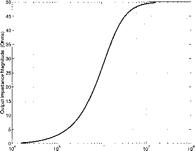 10° Frequency (Hz) FIGURE 31.3 LISN output impedance magnitude for a low impedance input source. 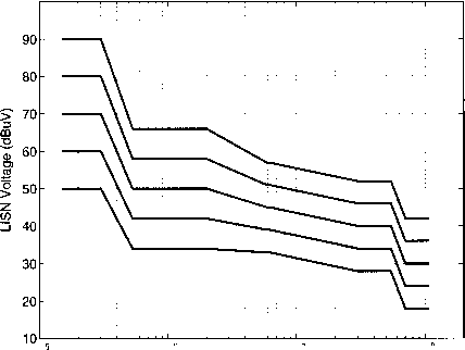 10 10 Frequency (Hz) 10° FIGURE 31.4 SAE J1113/41 narrow-band conducted EMI limits for power leads. The specification covers the frequency range from 150 kHz to 108 MHz. application. The equipment under test is then evaluated for transient behavior at turn on, turn off, and across its operating range. The voltage transients at the input of the equipment are measured and evaluated with respect to magnitude, duration, and rise and fall times. Specific limits for such transients are specified by the vehicle manufacturer, but SAE Jl 113/42 proposes a representative set of limits for four different transient severity levels. Due to the tight conducted emissions hmits, input EMI filter design is an important consideration in automotive power electronics. Single or multistage low-pass filters are typically used to attenuate converter ripple to acceptable levels [11-13]. When designing such filters, the parasitic behavior of the filter components, such as capacitor equivalent series resistance and inductance, and suitable filter damping are important considerations [14]. One must also ensure that the filter design yields acceptable transients at switch on and off, and does not result in undesired dynamic interactions with the power circuit [13]. Attention to appropriate filter design, coupled with proper circuit layout, grounding, and shielding goes a long way towards meeting electromagnetic interference specifications [14]. 31.3.4 Environmental Considerations The automobile is a very challenging environment for electronics. Environmental factors influencing the design of auto- motive electronics include temperature, humidity, mechanical shock, vibration, immersion, salt spray, and exposure to sand, gravel, oil and other chemicals. In 1978, the Society of Automotive Engineers developed a recommended practice for electronic equipment design to address these environmental considerations [3, 4]. This document, SAE J1211, provides quantitative information about the automotive environment to aid the designer in developing environmental design goals for electronic equipment. Here we briefly summarize a few of the most important factors affecting the design of power electronics for automotive applications. For more detailed guidelines, the reader is referred to [3] and the documents cited therein. Perhaps the most challenging environmental characteristic is the extreme range of temperatures that can occur in the automobile. Table 31.4 summarises some of the temperature extremes listed in SAE J1211 for different locations in the automobile. Ambient temperatures as low as -40° С may be found during operation, and storage temperatures as low as -50° С may be found for components shipped in unheated aircraft. Maximum ambient temperatures vary widely depending on vehicle location, even for small differences in position. Because ambient temperature has a strong impact on the design of a power electronic system it is important to work closely with the vehicle manufacturer to establish temperature specifications for a particular application. For equipment that is air-cooled one must also consider that the equipment may TABLE 31A Automotive temperature extremes by location [3]
onmental factors, sample recorded data, and recommended test procedures can be found in [3]. 31.4 Functions Enabled by Power Electronics Over the past 20 years power electronics has played a major role in the introduction of new functions such as the antilock breaking system (ABS), traction control and active suspension, as weU as the electrification of existing functions such as the engine-cooling fan, in the automobile. This trend is expected to continue, as a large number of new features being considered for introduction into automobiles require power electronics. This section discusses some of the new functions that have been enabled by power electronics, and some existing ones that benefit from it. be operated at altitudes up to 12,000 feet above sea level. This results in low ambient pressure (down to 9psia), which can reduce the heat transfer efficiency [3]. For equipment utilizing the radiator-cooling loop, maximum coolant temperatures in the range of 105-120° С at a pressure of 1.4 bar are possible [15]. In addition to the temperature extremes in the automobile, thermal cycling and shock are also important considerations due to their effect on component reliability. Thermal cycling refers to the cumulative effects of many transitions between temperature extremes, while thermal shock refers to rapid transitions between temperature extremes, as may happen when a component operating at high temperature is suddenly cooled by water splash. The damaging effects of thermal cycling and shock include failures caused by thermal expansion mismatches between materials. Test methods have been developed which are designed to expose such weaknesses [3, 16]. The thermal environment in the automobile, including the temperature extremes, cycling, and shock, are challenging issues that must be addressed in the design of automotive power electronics. A number of other important environmental factors exist in the automobile. FLumidity levels as high as 98% at 38°С can exist in some areas of the automobile, and frost can occur in situations where the temperature drops rapidly. Salt atmosphere, spray, water splash and immersion are also important factors for exterior, chassis, and underhood components. Failure mechanisms resulting from these factors include corrosion and circuit bridging. Dust, sand and gravel bombardment can also be significant effects, depending on equipment location. Mechanical vibration and shock are also important considerations in the design of automotive power electronic equipment. Details about the effects of these envir- 31.4.1 High Intensity Discharge Lamps FLigh intensity discharge (HID) lamps have started to appear in automobiles as low-beam headlights and fog lights. HID lamps offer higher luminous efficacy, higher reliability, longer life and greater styling flexibility than the traditional halogen lamps [17, 18]. The luminous efficacy of an HID lamp is over three times that of a halogen lamp and its hfe is about 2,000 hours, compared to 300-700 hours for a halogen lamp. Therefore, HID lamps provide substantially higher road illumination while consuming the same amount of electrical power and, in most cases, should last the life of the automobile. HID lamps also produce a whiter light than halogen lamps since their color spectrum is closer to that of the sun. HID lamps do not have a filament. Instead, light is generated by disharging an arc through a pressurized mixture of mercury, xenon and vaporized metal hahdes - mercury produces most of the light, the metal hahdes determine the color spectrum, and xenon helps reduce the start-up time of the lamp [17, 19]. Unlike halogen lamps that can be powered directly from the 12 V electrical system, HID lamps require power electronic baUasts for their operation. Initially, a high voltage pulse of 10-30 kV is needed to ignite the arc between the electrodes and a voltage of about 85 V is needed to sustain the arc [19]. Figure 31.5 shows a simplified power electronic circuit that can be used to start and drive an HID lamp. A step-up dc-dc converter is used to boost the voltage from 12 V to the voltage needed for the steady state operation of the HID lamp. Any dc-dc converter that can step up the voltage, such as the boost or flyback converter, can be used for this application. An H-bridge is then used to create the ac voltage that drives the lamp in steady state. The circuit to initiate the arc can be as simple as a circuit that provides an inductive voltage kick, as shown in Fig. 31.5. 12 V 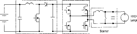 Boost converter H-bridge FIGURE 31.5 Simplified power electronic circuit for an HID lamp ballast. 31.4.2 Pulse-Width Modulated Incandescent Lighting Future automobiles may utilize a 42 V electrical system in place of todays 14 V electrical system (see Section 31.7). Because HID lamps are driven through a power electronic ballast, HID lighting systems operable from a 42 V bus can easily be developed. However, the high cost of HID lighting - as much as an order of magnitude more expensive than incandescent lighting - largely hmits its usefulness to headlight apphcations. Incandescent lamps compatible with 42 V systems can also be implemented. However, because a much longer, thinner filament must be employed at the higher voltage, lamp lifetime suffers greatly. An alternative to this approach is to use pulse-width modulation to operate 12 V incandescent lamps from a 42 V bus [20]. In a pulse-width modulated (PWM) Lighting system, a semiconductor switch is modulated to apply a periodic pulsed voltage to the lamp filament. Because of its resistive nature, the power delivered to the filament depends on the rms of the applied voltage waveform. The thermal mass of the system filters the power pulsations so that the filament temperature and light production are similar to that generated by a dc voltage with the same rms value. The PWM frequency is selected low enough to avoid lamp mechanical resonances and the need for EMI filtering, while being high enough to limit visible flicker; PWM frequencies in the range of 96-250 Hz are typical [20]. Ideally, a 11.1% duty ratio is needed to generate 14 V rms across a lamp from a 42 V nominal voltage source. In practice deviations from this duty ratio are needed to adjust for input voltage variations and device drops. In some proposed systems, multiple lamps are operated within a single lighting module with phase staggered (interleaved) PWM waveforms to reduce the input rms current of the module. Another issue with PWM lighting relates to startup. Even with operation from a 12 V dc source, incandescent lamps have an inrush current that is 6-8 times higher than the steady-state value, because of how filament resistance changes with temperature; this inrush impacts lamp durability. The additional increase in peak inrush current due to operating from a 42 V source can be sufficient to cause destruction of the filament, even when using conventional PWM soft-start techniques (a ramping up of duty ratio). Means for limiting the peak inrush current - such as operating the controlling MOSFET in current limiting mode during startup - are needed to make practical use of PWM lighting control. While PWM incandescent lighting technology is still in the early stages of development, it offers a number of promising advantages in future 42 V vehicles. These include low-cost adaptation of incandescent lighting to high-voltage systems, control of lighting intensity independent of bus voltage, the ability to implement multiple intensities, flashing, dimming, etc., through PWM control, and the potential improvement of lamp durability through more precise inrush and operating control [20]. 31.4.3 Piezoelectric Ultrasonic Actuators Piezoelectric ultrasonic motors are being considered as actuators for window lifts, seat positioning, and head restraints in automobiles [21, 22]. These motors work on the principle of converting piezoelectrically induced ultrasonic vibrations in an elastic body into unidirectional motion of a moving part. Unidirectional motion is achieved by allowing the vibrating body to make contact with the moving part only during a half cycle of its oscillation, and power is transferred from the vibrating body to the moving part through frictional contact. Ultrasonic motors have a number of attractive features, including high torque density, large holding torque even without input power, low speed without gears, quiet operation, no magnetic fields and high dynamics [21, 23]. These characteristics make ultrasonic motors an attractive alternative to electromagnetic motors for low-power high-torque applications. Various types of ultrasonic motors have been developed. However, because of its compact design the traveling wave type is the most popular ultrasonic motor [24]. Figure 31.6(a) shows the basic structure of such a motor. It consists of a metal stator and rotor, which are pushed against each other by a spring. The rotor is coated with a special fining material to increase friction and reduce wear at the contacting surfaces. A layer of piezoelectric material, such as lead zirconate titanate neutral plane spacer segment 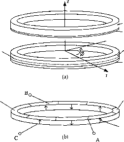 metal ring lining material metal ring piezoelectric ceramic spacer segment rotor stator poling direction FIGURE 31.6 (a) Basic structure of a traveling wave piezoelectric ultrasonic motor, (b) Structure of the piezoceramic ring and electrode for a four-wavelength motor. Arrows indicate direction of polarization. Dashed lines indicate segments etched in the electrode for poling but electrically connected during motor operation. (PZT), is bonded to the underside of the stator. Silver electrodes are printed on both sides of the piezoceramic ring. The top electrode is segmented and the piezoceramic is polarized as shown in Fig. 31.6(b). The number of segments is twice the order of the excited vibration mode. When a positive voltage is applied between terminals A and C, the downwards poled segment elongates and the upwards poled segments contract. This causes the stator to undulate, waving down at the elongated section and up at the contracted one. When the polarity of the voltage is inverted, the undulations are also inverted. Fience, when an ac voltage is apphed a flexural standing wave is created in the stator. To get a large wave amplitude the stator is driven at the resonance frequency of the flexural mode. An ac voltage between terminals В and С similarly produces another standing wave. Fiowever, because of the spacer segments in the piezoceramic ring, the second standing wave is 90° spatially out of phase from the first one. If the two standing waves are excited by ac voltages that are out of phase in time by 90°, a traveling wave is generated. As the traveling wave passes through a point along the neutral plane, that points simply exhibits axial (z-axis) motion. Fiowever, off-neutral plane points also have an azimuthal (ф-axis) component of motion. This azimuthal motion of the surface points propels the rotor. Ultrasonic motors require a power electronic drive. A power electronic circuit suitable for driving an ultrasonic motor is shown in Fig. 31.7. The two Fi bridges are controlled to generate waveforms that are 90° out of phase with each other. 12 V 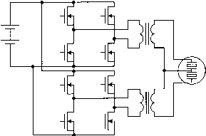 Ultrasonic Motor FIGURE 31.7 Drive circuit for an ultrasonic motor. 31.4.4 Electromechanical Engine Valves Electromagnetic actuators are finding increasing application in automotive systems. These actuators are more desirable than other types of actuators, such as hydraulic and pneumatic actuators, because they can be more easily controlled by a microprocessor to provide more precise control. An application of electromagnetic actuators that is of particular interest is the replacement of the camshaft and tappet valve assembly by electromechanically driven engine valves [25]. The opening and closing of the intake and exhaust valves can be controlled to achieve optimum engine performance and improved fuel economy over a wide range of conditions determined by variables such as the speed, load, altitude and temperature. 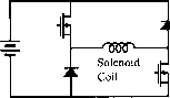 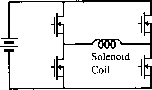 (a) (b) FIGURE 31.8 Power electronic circuits for driving solenoids. The present cam system provides a valve profile that can give optimum engine performance and improved fuel economy only under certain conditions. Two power electronic circuits suitable for driving the solenoids for valve actuation are shown in Fig. 31.8. The circuit of Fig. 31.8(a) is suitable for solenoids that require unidirectional currents through their coils, while the circuit of Fig. 31.8(b) is suitable for solenoids that require bidirectional currents through their coils. 31.4.6 Electric and Electro-Hydraulic Power Steering Systems The hydraulic power steering system of a vehicle is another example of an engine-driven accessory. This system can be replaced with an electric power steering (EPS) system in which a brushless dc motor is used to provide the steering power assist [27]. The electric power steering system is more efficient than the hydraulic power steering system because, unlike the engine-driven hydraulic steering pump which is driven by the engine all of the time, the motor operates only on demand. Another system that can replace the hydraulic power steering system is the electro-hydraulic power steering (EHPS) system. In this case, a brushless dc motor and inverter can he employed to drive the hydraulic steering pump. The ability of the electro-hydraulic power steering system to drive the pump only on demand leads to energy savings of as much as 80% as compared with the conventional hydraulic system. Challenges in implementing EPS and EPHS systems include meeting the required levels of cost and reliability for this critical vehicle subsystem. 31.4.5 Electric Air Conditioner It is desirable to replace some of the engine-driven functions of a vehicle with electrically driven counterparts. The benefits of driving these functions electrically include the ehmination of belts and pulleys, improved design and control due to independence from engine speed, and resulting increased efficiency and improved fuel economy. Furthermore, there is the opportunity for operation of the function in the engine-off condition. The air conditioner is an example of an engine-driven function that could benefit from electrification. The engine drives the compressor of the air conditioner. Consequently, the speed of the compressor varies over a wide range and the compressor has to be over-sized to provide the desired performance at engine idle. Also, since the compressor speed is dependent on the engine speed, excessive cooling occurs at highway speeds requiring the cool air to be blended with the hot air to keep the temperature at the desired level. Furthermore, shaft seals and rubber hoses can lead to the loss of refrigerant (CFC) and pose an environmental challenge. In an electric air conditioner, an electric motor is used to drive the compressor [26]. The motor is usually a three-phase brushless dc motor driven by a three-phase MOSFET bridge. The speed of the compressor in an electric air conditioner is independent of the engine speed. As a result, the compressor does not have to be over-sized and excessive cooling does not occur. Also, shaft seals and hoses can be replaced with a hermetically sealed system. Another benefit of an electric air conditioner is the flexibility in its location, since it does not have to be driven by the engine. 31.4.7 Motor Speed Control Some of the motors used in a vehicle require variable speed control. Consider, as an example, the blower motor used to provide air flow to the passenger compartment. This motor is typically a permanent-magnet dc motor with a squirrel-cage fan. The speed of the motor is usually controlled by varying the resistance connected in series with the motor winding. This method of speed control leads to a significant power loss. A low-loss method of speed control employs semiconductor devices as shown in Fig. 31.9. In this case, the speed of the motor is controlled via pulse-width modulation (PWM) - that is, by switching the MOSFET on and off with different duty ratios for different speed settings. An input filter is needed to reduce the EMI generated by the switching of the MOSFET. This method of speed control is equivalent to supplying power to the motor through a variable-output dc-to-dc converter. The converter is located close to the motor and no filter is required between the converter output and motor winding. Another low-loss method that can be used to control the speed of a motor employs a three-phase brushless dc motor. The speed in this case is controlled by controlling the MOSFETs in the dc-to-three-phase-ac converter that drives the motor. 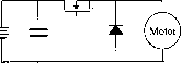 FIGURE 31.9 Low-loss circuit to control the speed of a motor. 31.5 Multiplexed Load Control Another emerging application of power electronics in automobiles is in the area of load control. In the conventional point-to-point wiring architecture most of the loads are controlled directly by the primary mechanical switches, as shown in Fig. 31.1. In a point-to-point wiring architecture each load has a dedicated wire connecting it to the fuse box via the primary switch. Consequently fairly heavy wires have to be routed aU over the vehicle, as illustrated in Fig. 31.10(a). The situation is made worse when multiple switches control the same load, as is the case with power windows and power door locks. The complete harness of a 1994 C-class Mercedes Benz that uses point-to-point wiring has about 1,000 wires, with a total length of 2 km, over 300 connectors and weighs 36 kg. The process of assembling the wiring harness is difficult and time consuming, leading to high labor costs. Retrofitting, fault tracing and repairing are time consuming and expensive. The о Alternator L2 Battery S5 S6 L3 -I- 0S4 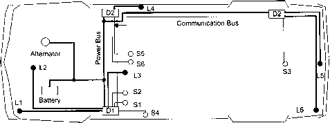 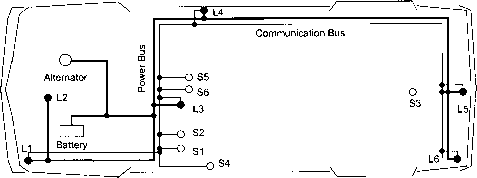 FIGURE 31.10 Alternative control strategies illustrated for a simple automotive electrical system with six loads (Ll-6) and six primary switches (Sl-6). (a) Conventional direct switching architecture with a single fusebox (Fl), (b) multiplexed remote switching architecture, with remote switches and transceivers in three distribution boxes (Dl-3), and (c) multiplexed point-of-load switching with electronics integrated into the loads and the primary switches. bulky harness also places constraints on the vehicle body design, and the large number of connectors compromise system reliability. An alternative wiring technique is to control the loads remotely and multiplex the control signals over a communication bus, as shown in Fig. 31.10(b) and (c). A control message is sent on the communication bus to switch a particular load on or off. This allows more flexibility in the layout of the power cables and could allow the preassembly of the harness to be more automated. Furthermore, with communication between the remote switches it is practical to have a power management system than can turn off nonessential loads when there is a power shortage. One possibility is to group the remote switches into strategically located distribution boxes, as shown in Fig. 31.10(b). A power and a communication bus connect the distribution boxes. Another possibility is to integrate the remote switches with the load, i.e. point-of-load switching, as shown in Fig. 31.10(c). In Fig. 31.10(b) the transceivers are also built into the distribution boxes, while in Fig. 31.10(c) each load and primary switch has an integrated transceiver. The point-of-load switching topology is attractive because of its simphcity, but raises cost and fusing challenges. Multiplexed remote switching architectures have been under consideration since at least the early 1970s, when Ziomek investigated their apphcation to various electrical subsystems [28]. The initial interest was dampened by cost and reliability concerns and the non-availability of appropriate remote switches. However, advances in semiconductor technology and rapid growth in the automotive electrical system revived interest in multiplexed architectures. The SAE Multiplexing Standards Committee has partitioned automotive communications into three classes: Class A for low data-rate (1-lOkbit/s) communication for the control of body functions, such as headlamps, windshield wipers and power windows. Class В for medium data-rate (10-100 kbit/s) parametric data exchange, and Class С for high data-rate (IMbit/s) real-time communication between safety critical functions, such as between ABS sensors and brake actuators [29]. Although load control is categorized as Class A, lack of any widely accepted Class A communication protocols has led to the application of Class В and Class С communication ICs to load control. Class В has received the most attention due to the California Air Resources Board mandated requirement for on-board diagnostics (OBD II) and a large number of competing protocols, including the French Vehicle-Area Network (VAN), ISO 9141 and SAE J1850, have been developed [30]. Of these the SAE J1850 is the most popular in the US. Another popular protocol is the Controller Area Network (CAN) developed by Bosch [31]. Although designed for Class С with bit rates up to 1 Mbit/s, it is being apphed for Class A and Class В applications due to the availability of inexpensive CAN ICs from a large number of semiconductor manufacturers. Remote switching systems require remote power switches. An ideal remote switch must have a low on-state voltage, be easy to drive from a microcontroller and incorporate current sensing. A low on-state voltage helps minimize the heatsinking requirements, while current sensing is needed for the circuit protection function to be incorporated into the switch. To withstand the harsh automotive environment the switch must also be rugged. Furthermore, if pulse width modulated (PWM) control is required for the load, the switch must have short turn-on and turn-off times and a high cycle life. The traditional means of remotely switching loads in an automobile is via electromechanical relays. Although relays offer the lowest voltage drop per unit cost, they require large drive current, are relatively large, are difficult to integrate with logic, and are not suitable for PWM applications [32, 33, 34]. Therefore, their use will be hmited to very high current, non-PWM applications. The power levels of the individual loads in the automobile are too low for IGBTs and MCTs to be competitive. Bipolar transistors are also not very attractive because they are harder to drive than a MOS-gated device. Because of its fast switching speed, low voltage drop, relative immunity to thermal runaway, low drive requirements and ease of integration with logic, the power MOSFET is the most attractive candidate for remote switching. Smart-power MOSFET devices with integrated logic interface and circuit protection have recently become available. Use of these devices for power electronic control of individual loads has become economically competitive in some subsystems, and may be expected to become more so with the advent of higher-voltage electrical systems. The benefits of remote switching electrical distribution systems have been demonstrated by Furuichi et al. [35]. The multiplexed architecture they implemented had 10 remote units (2 power units with fuses, power drivers and signal inputs, 5 load control units with power drivers and signal inputs but no fuses, and 3 signal input units with only signal inputs). To increase system reliability, each power unit was connected to the battery via independently fused power cables. Although wiring cost decreased, the authors report an increase TABLE 31.5 Comparison of a multiplexed and the conventional system, as reported by Furuichi et al for a compact vehicle [35]. In the multiplexed system the function of nine electronic control units (ECUs) was integrated into the remote units Point-to-Point Multiplexed Change (%)
1 ... 77 78 79 80 81 82 83 ... 91 |
|
© 2026 AutoElektrix.ru
Частичное копирование материалов разрешено при условии активной ссылки |