 |
 |
 |
| Главная Журналы Популярное Audi - почему их так назвали? Как появилась марка Bmw? Откуда появился Lexus? Достижения и устремления Mercedes-Benz Первые модели Chevrolet Электромобиль Nissan Leaf |
Главная » Журналы » Metal oxide semiconductor 1 ... 78 79 80 81 82 83 84 ... 91 in overall system cost due to the additional cost of the remote units. Intels CAN ICs with data rates of 20kbit/s were used for the transmission and reception of control signals over an unshielded twisted-pair ring bus. Intelhgent power MOSFETs were used as the remote switches and fusing was done with minifuses. The results of their work are shown in Table 31.5. Although weight of the wiring harness was reduced by 30%. the total system weight decreased by only 12.5% due to the added weight of the remote units. 31.6 Electromechanical Power Conversion Power is generated in the automobile by an electrical machine driven by the engine. In the early days of the automobile, the electrical load was small and a dc generator was used for this purpose. As the electrical loads grew, the dc generator could not meet the growing demand of electrical power and was displaced by a three-phase alternator and diode rectifier. Continuously increasing power and performance requirements are driving further evolution in automotive power generation and control, and are motivating the introduction of power electronics and improved electrical machines in automobiles. In addition to high-power alternators, future apphcations of electromechanical power conversion may include integrated starter/alternators and propulsion systems. This section describes some of the machine and power electronic technologies that are useful for meeting the increasing chaUenges in the automobile. brushes, and causes the two pole pieces to become opposing magnetic poles. A fuU-bridge diode rectifier is traditionally used at the machine output, and a fan mounted on the rotor is typically used to cool the whole assembly. The dc output vohage of the alternator system is regulated by controlling the field current. A switching field regulator applies a pulse-width modulated voltage across the field. The steady-state field current is determined by the field winding resistance and the average voltage applied by the regulator. Changes in the field current occur with an L/R field winding time constant on the order of 100 ms or more. This long field-winding time constant and a large stator leakage reactance are characteristic of this type of alternator and tend to dominate its performance. The alternator is driven by means of a belt, and is designed to operate over a wide speed ratio of about 10:1, though much of its operating lifetime is spent within a narrower 3 :1 or 4:1 range. The gearing ratio provided by the belt is a design variable for the alternator; an alternator mechanical speed range from 1,800 rpm to 18,000 rpm for a 12-pole machine is typical. A simple electrical model for the LundeU alternator is shown in Fig. 31.12. The armature of the alternator is modeled as a Y-connected set of leakage inductances L and back voltages isa, isb, and v. The fundamental electrical frequency Ш of the back emfs is one half of the product of the number of machine poles p and the mechanical speed oj. The magnitude of the back emfs is proportional to the electrical frequency and the field current. For the sinusoidal case, the line-to-neutral voltage back emf magnitude can be calculated as 31.6.1 The Lundell Alternator The LundeU, or claw-pole, alternator is a three-phase wound-field synchronous machine that is almost universally used for power generation in present-day vehicles [1]. As iUustrated in Fig. 31.11, the rotor is made of a pair of stamped pole pieces ( claw poles ) fixed around a cylindrical field coU. The field winding is driven from the stator via a pair of shp rings and (31.1) where к is the machine constant and ц is the field current. The diode bridge feeds a constant voltage Vq representing the battery and other loads. This simple model captures many of the important characteristics of the LundeU alternator, whUe remaining analytically tractable. Other effects, such as stator 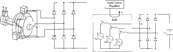 FIGURE 31.11 ahernator. Structure and circuitry of the conventional Lundell Battery FIGURE 31.12 A simple Lundell ahernator model. resistance, mutual coupling, magnetic saturation and waveform harmonic content, can be incorporated into this model at the expense of simplicity. The constant-voltage battery load on the alternator makes the analysis of this system different from the classic case of a diode rectifier with a current-source load. Nevertheless, with reasonable approximations, the behavior of this system can be described analytically [8]. Using the results presented in [8], alternator output power vs. operating point can be calculated as transiently impressed across the alternator output when the load is suddenly reduced. The efficiency of the conventional Lundell alternator is relatively poor. Typical efficiency values are of the order of 40-60%, depending on operating point [1, 36, 37]. At low and medium speeds, losses tend to be dominated by stator copper losses. Iron losses become dominant only at very high speeds [1]. (31.2) where Vq is the output voltage, is the back emf magnitude, CO is the electrical frequency, and is the armature leakage inductance. Extensions of (31.2) that also include the effect of the stator resistance are given in [8]. As can be inferred from (31.2), alternator output power varies with speed, and is maximized when the back emf magnitude of the machine is substantially larger than the output voltage. In a typical Lundell alternator back voltages in excess of 80 V may be necessary to source rated current into a 14 V output at high speed. Furthermore, as can be seen from (31.2), the armature leakage reactance limits the output power capability of the alternator. These characteristics are a result of the fact that significant voltage drops occur across the leakage reactances when current is drawn from the machine. These drops increase with speed and current, and cause the alternator to exhibit significant droop in output voltage with increasing current. Thus, an appropriate dc-side model for a Lundell alternator is a large open-circuit voltage (related to the back emf magnitude) in series with a large current and speed dependent output impedance. This characteristic, coupled with the long field time constant, is the source of the undesirable load-dump transient characteristic of the Lundell alternator. In this transient the large open-circuit voltage is 31.6.2 Advanced Lundell Alternator Design Techniques The conventional diode-rectified Lundell alternator, though inefficient, has so far met vehicle electrical power requirements in a cost-effective manner. However, continuing increase in electrical power demand and growing interest in improved fuel economy is pushing the limits of conventional Lundell alternator technology. This section describes some established and some emerging technologies that can be used to improve the performance of the Lundell alternator. 31.6.2.1 Third Harmonic Booster Diodes One widely used approach for improving the high-speed output power capability of Lundell alternators is the introduction of third-harmonic booster diodes [ 1 ]. In this technique, the neutral point of the Y-connected stator winding is coupled to the output via a fourth diode leg, as illustrated in Fig. 31.13. While the fundamental components of the line-to-neutral back voltages are displaced by 120° in phase, any third harmonic components will be exactly in phase. As a result, third harmonic energy can be drawn from the alternator and transferred to the output by inducing and rectifying common-mode third harmonic currents through the three windings. The booster diodes provide a means for achieving this. At high speed, the combination of the third harmonic voltages at the Field Current Regulator field A i i i ZX A s Battery FIGURE 31.13 Lundell alternator with booster diodes. main rectifier bridge (at nodes a, b, and с in Fig. 31.13), combined with the third harmonic of the back voltages, are large enough to forward bias the booster diodes and deliver third harmonic energy to the output. In systems with significant (e.g. 10%) third harmonic voltage content, up to 10% additional output power can be delivered at high speed. Additional power is not achieved at low speed, or in cases where the third harmonic of the back voltage is smaU. 31.6.2.2 Lundell Alternator with Permanent Magnets The structure of the rotor of the claw-pole alternator is such that the leakage flux is high. This reduces the output current capability of the alternator. The leakage flux can be reduced by placing permanent magnets on the pole faces or in the spaces between the adjacent poles of the rotor. This modification allows the alternator to deliver more output current. Placing the magnets in the spaces between adjacent poles is a better approach because it is simpler to implement and leads to a higher output current at engine idle [38]. 31.6.2.3 Twin-Rotor Lundell Alternator The maximum power capability of the Lundell alternator is limited in part by the limit on its length-to-diameter ratio imposed by mechanical stresses on the stamped pole pieces. This prevents the Lundell alternator from being arbitrarily scaled up in size. The power capability of conventional designs is probably limited to 3 kW, which is likely to be unacceptable in the foreseeable future [39]. One way to retain the cost-effectiveness of the claw-pole alternator while achieving higher output power is to place two claw-pole rotors back-to-back on a common shaft inside a common stator [40]. This effectively increases the length of the claw-pole alternator without changing its diameter. This design aUows higher power alternators to be built while retaining most of the cost benefits of the claw-pole design. 31.6.2.4 Power Electronic Control Another approach for improving the output power and efficiency of the Lundell alternator is through the use of more sophisticated power electronics. Power electronics technology offers tremendous value in this application. For example, replacing the conventional diode rectifier with a switched-mode rectifier provides an additional degree of design and control freedom, and aUows substantially higher levels of power and efficiency to be attained from a given machine. One such design is shown in Fig. 31.14. It employs a simple switched-mode rectifier along with a special load-matching control technique to achieve dramatic improvement in alternator output power, efficiency, and transient performance [37]. The switched-mode rectifier provides improved control without the cost and complexity of a fuU active converter bridge. By controlhng the duty ratio of the switched-mode rectifier based on available signals such as alternator speed, the alternator output power characteristic (31.2) can be altered and improved, particularly for speeds above idle [37]. Improvements in average power capability of a factor of two and average efficiency improvements on the order of 20% are possible with this technology. Furthermore, the switched-mode rectifier can be employed to achieve greatly improved load-dump transient control. 31.6.3 Alternative Machines and Power Electronics The demand for increased alternator power levels, efficiency, and performance also motivates the consideration of alternative electrical machines, power electronics, and design approaches. While no alternative machine has yet displaced the Lundell alternator in production vehicles, primarily due to cost considerations, some potential candidates are reviewed in this section. These include machines that are mounted directly on the engine rather than driven from a belt. These direct drive machines become important as power levels rise. This 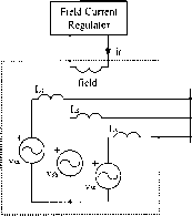 Щ # Й Battery FIGURE 31.14 Lundell ahernator with a switched-mode rectifier. section also addresses the more general case of the combined starter/alternator. While the use of a single machine to do both starting and generation functions is clearly possible, a separate (transient-rated) dc machine is presently used for starting. This is because the large mismatch in starting and generating requirements has made the combined starter/ alternator approach unattractive. However, as alternator power ratings increase the mismatch is reduced, and a single starter/alternator system becomes more practical. A combined system has the potential to ehminate the need for a separate flywheel, starter, solenoid switch, and pinion engaging drive. It also has the potential to allow regenerative braking and light hybrid operation, and to provide idle-stop capability (i.e. the ability to turn off the engine when the vehicle is stopped and seamlessly restart when the vehicle needs to move) for reduced fuel consumption. A move to this more sophisticated approach relies upon advanced electrical machines and power electronics. 31.6.3.1 Synchronous Machine with a Cylindrical Wound Rotor The claw-pole rotor can be replaced with a cylindrical rotor to achieve better couphng between the stator and rotor. The cyhndrical rotor is made from steel laminations and the field winding is placed in the rotor slots. The cyhndrical rotor is similar to the armature of a dc machine except that the connection of the field winding to the external circuit is made through slip rings instead of a commutator. The cyhndrical rotor structure leads to quiet operation and increased output power and efficiency. Unlike the claw-pole alternator, the length of the machine can be increased to get higher output power at a higher efficiency. The efficiency is higher since the effect of the end windings on the machine performance is less in a machine with a long length. It is also possible to build the machine with a salient-pole rotor instead of a cylindrical rotor. However, a machine with a salient-pole rotor is likely to produce more noise than a machine with a cyhndrical rotor. A machine with a cyhndrical wound rotor has similar power electronics and control options as a claw-pole machine. If generation-only operation is required, a diode bridge and field current control is sufficient to regulate the output voltage. Better performance can be achieved by using a switched-mode rectifier in conjunction with field control [37]. If motoring operation is desired (e.g. for starting), or even better performance is desired, a full-bridge (active-switch) converter can be used, as shown in Fig. 31.15. Since this is a synchronous machine some form of rotor position sensing or estimation is typically necessary. The full bridge converter allows maximum performance and flexibility but carries a significant cost penalty. 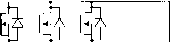  FIGURE 31.15 Model of an alternator with fuU bridge converter. 31.6.3.2 Induction Machine The stator of a three-phase induction machine is similar to that of a three-phase synchronous machine. The rotor is either a squirrel-cage or wound rotor. The machine with the squirrel-cage rotor is simpler in construction and more robust than the machine with a wound rotor in which the three-phase rotor winding is brought outside the rotor through slip rings. The rotor is cyhndrical and is constructed from steel laminations. It is also possible to use a sohd rotor instead of a laminated rotor. However, a solid rotor leads to higher losses as compared with a laminated rotor. The losses in a solid rotor can be reduced by cutting slots in the rotor surface, filling the stator slot openings with magnetic wedges to reduce the field ripple, and placing a copper cage on the rotor. An induction machine requires a source that can provide the leading reactive power to magnetize the air gap. This means that a three-phase induction generator cannot supply power to a load through a three-phase diode bridge. Capacitor supply of the reactive energy is impractical because of the wide operating speed range. In the most general case (in which both motoring and generating operation can be achieved) a three-phase active bridge can be used. If only generating operation is desired, the power to the load can be supphed through a three-phase diode bridge and the reactive power can be obtained from a small three-phase active bridge provided for this purpose. This design requires a large number of devices and complex control. 31.6.3.3 Reluctance Machines The switched reluctance machine is a doubly sahent machine. Both the stator and rotor of the machine are made from steel laminations to reduce the iron losses. Only the stator carries windings; the rotor is constructed of steel laminations with a salient shape. The structure of a three-phase switched reluctance machine with six stator poles and four rotor poles is shown in Fig. 31.16(a). A winding placed on diametrically opposite stator poles forms a phase winding. When a phase of the machine is excited, a pair of rotor poles tends to align with the excited stator poles to provide a path of minimum reluctance. If the rotor is moving towards alignment with the excited pair of stator poles, then the machine develops a 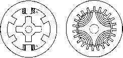 FIGURE 31.16 Structures of (a) switched reluctance and (b) synchronous reluctance machines. AA represents phase A winding. positive torque and acts as a motor. If the rotor is moving away from the excited pair of stator poles, then the machine develops a negative torque and acts as a generator. The advantages of the switched reluctance machine include simple construction, fault-tolerant power electronic circuit, high reliability, unidirectional phase currents and low cost. The drawbacks of the machine include high levels of torque ripple, vibration and acoustic noise, and a relatively high power electronics cost. The synchronous reluctance machine is a singly salient machine. The stator of the machine is similar to that of a synchronous or induction machine. The rotor has a segmented structure with each segment consisting of a stack of axially-laminated steel sheets sandwiched with a non-magnetic material. The structure of a four-pole synchronous reluctance machine is shown in Fig. 31.16(b). A synchronous reluctance machine has less torque ripple, lower losses and higher power density than a comparable switched reluctance machine. Inclusion of permanent magnets in the rotor structure allows both reluctance and magnet torque to be achieved. Such Interior Permanent Magnet (IPM) machines can achieve very high performance and power density. When permanent magnets are included, however, careful attention must be paid to the effects of shutdown of the power electronics as an uncontroUed back emf component wiU exist in this case [41]. The switched reluctance machine, like the induction machine, requires an external source to magnetize the air gap. Several circuits are available to excite the switched reluctance machine. A circuit that is suitable for the automotive application of this machine is shown in Fig. 31.17. A Phase A Phase В Phase С FIGURE 31.17 Circuit for a switched reluctance machine. phase leg is needed for each stator phase of the machine. In this case, the switched reluctance machine obtains its excitation from the same bus that it generates into. Unlike the synchronous and induction machines in which the number of wires needed to connect the machines to the power converters is usually equal to the number of phases, the number of wires needed to connect the switched reluctance machine to a converter is equal to twice the number of phases. This is of no particular concern in a switched reluctance machine in which the power converter is integrated with the machine in the same housing. The synchronous reluctance machine also requires an external source to magnetize the air gap. The machine usually employs an active bridge simUar to the one used with an induction machine for the desired power conversion. The machine can also employ the converters used with the switched reluctance machine. In this case, the currents through the stator windings are unidirectional. The relative complexity of the power electronics is a disadvantage of these machine types in the case where only generator operation is necessary. 31.6.3.4 Permanent-Magnet and Hybrid Synchronous Machines The permanent-magnet synchronous machine designed with high-energy rare-earth magnets operates with high efficiency, high power density, low rotor inertia and low acoustic noise. The excitation from the permanent magnets is fixed and, therefore, the regulation of the output voltage of the machine is not as straightforward as in a synchronous machine with a wound rotor. For generator operation, machines of this type can use switched-mode rectifiers to regulate the output voltage [42, 43]. The boost rectifier of Fig. 31.14 is one possible implementation of this approach. Alternatively, a diode rectifier foUowed by a dc/dc converter can be used to regulate the generator system output [44]. Another method proposed for this type of system involves the use of tapped windings and two three-phase SCR bridges [45]. The taps on the phase windings are connected to one bridge, whUe fuU phase windings are connected to the other bridge. The bridge connected to the fuU phase windings is used to supply power to the dc bus at low engine speeds, while the converter connected to the taps is used at high speed. The use of a tapped winding and dual bridges helps the system cope with the wide speed range of the alternator and limit the losses associated with the pulsating output currents. In the case when both motoring and generating modes are desired, a fuU-bridge converter can be used. Again, as this is a synchronous machine, some form of position sensing or estimation is necessary. Also, in aU of these systems the effects of faUure of the power electronics must be carefully considered as there is no possibUity of regulating the back voltages by field control. Attempts to develop a simpler voltage regulation scheme for permanent-magnet synchronous machines have led to a per- manent-magnet/wound-rotor hybrid synchronous machine in which the rotor consists of two parts: a part with permanent magnets and a part with a field winding [46]. The two parts are placed next to each other on a common shaft. The rotor with the field winding can employ claw-pole, salient-pole, or cyhndrical structure. The field current generates a flux that is used to either aid or oppose the permanent magnet flux and regulate the output voltage of the machine. One possible failure mode of this approach that can lead to catastrophic failure is if the field winding breaks while the machine is operating at high speed. In this case, the generated output voltage will become large and uncontrolled. Some means of mechanically disconnecting the alternator at the input or electrically disconnecting it at the output may be necessary to limit the impact of this failure mode. 31.6.3.5 Axial-Airgap Machines The principle of operation of an axial-air gap, or axial-flux, machine is the same as that of a radial-airgap machine. An axial-airgap machine is characterized by a short axial length and large diameter. The structure of an axial-airgap permanent-magnet machine with surface magnets is shown in Fig. 31.18 [47]. The stator of the machine can be slotless or slotted. Two different magnetic circuit configurations are possible. In the NN configuration, the magnetic polarities in one pole pitch on both sides of stator are the same so that there are two main fluxes with symmetrical distribution through the stator. In this case, the conductors can be wound into two back-to-back stator slots to make one coil. The machine has a large stator yoke dimension because the flux passes through the yoke, but less copper loss because of short end windings. In the NS configuration, the magnetic polarities in one pole pitch on the opposite sides of stator are the opposite of each other so that there is only one main axial flux through the stator. In this case, the stator yoke dimension is small, but the end windings are long because the direction of current in the hack-  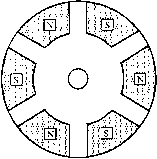 Stator И Magnets Rotor Shaft FIGURE 31.18 Structure of an axial-airgap permanent-magnet machine. to-back stator slots is the same. The iron losses are small due to small yoke dimension and the copper losses are high because of long end windings. Heat removal is more challenging due to small stator dimensions. The structure shown in Fig. 31.18 is that of an axial-airgap permanent-magnet machine with surface magnets. In an axial-airgap machine with interior permanent magnets, the magnets are embedded in the steel of the rotor. The axial-air gap versions of other types of machines, such as the induction and switched reluctance machines, are also possible. The structure of an axial-air gap induction machine is similar to that of an axial-airgap permanent-magnet machine except that windings are used instead of permanent magnets, 31.7 Dual/High-Voltage Automotive Electrical Systems The electrical system of a 1920s internal-combustion-engine (ICE) automobile had only a few loads: a starter, an ignition device, a horn, and some lamps [48]. The mean power consumption of these loads was less than 100 W. An engine driven dc generator charged a 6V lead-acid battery that provided electrical power. The power was distributed via point-to-point wiring, with most loads controlled directly by manually operated primary switches located within reach of the driver. Only the starter was switched indirectly by an electromechanical relay. After the Second World War, the automotive electrical system started to grow rapidly in complexity and power consumption as additional features, including radios, multispeed windshield wipers and power windows, were added. The introduction of higher compression engines stretched the 6 V system beyond its technological hmits. The 8.5 to 1 compression ratio engines required 100-200% greater ignition voltages than the 6.4 to 1 engines. As a result, the primary side current of the ignition coil was doubled or tripled and the life of the distributor contacts was reduced to an unacceptable level. To overcome this problem the battery voltage was increased to 12 V in the mid-1950s [49, 50]. Over the past four decades the electrical power requirements of automobiles have increased even more rapidly. From a mere 400 W in 1955, the power rating of a luxury vehicles generator has increased to over 1,800 W [51, 52]. However, the electrical system of a modern automobile is architecturally identical to the 12 V point-to-point system of the 1950s. The only changes that have taken place have been at the component level, such as the replacement of the dc generator by a three-phase alternator-rectifier, the replacement of wound-field dc motors by permanent-magnet ones, and an increased use of relays. The rapid growth in the electrical system is expected to continue due to environmental regulations, consumer demand for increased functionality, safety, security. and comfort, and replacement of some mechanical actuators by electrical counterparts. The average electrical power requirement of a modern luxury vehicle is about 800 W. With the addition of such loads as electric power steering, engine-cooling fan, water pump and electro-mechanical engine valves, the average power requirement could increase to 2.5 kW by 2005 [53]. The traditional solution of increasing the size of the alternator and the battery is not practical due to space limitations and fuel efficiency requirements. Furthermore, the peak power requirements of some of the anticipated loads -heated windshield (2.5 kW), heated catalyst (3kW), electro-mechanical engine valves (2.4 kW at 3,000 rpm) and active suspension (12 kW) - cannot be met economically using the present architecture. These factors have motivated the development of new dual/high-voltage electrical architectures that incorporate a higher-voltage bus in addition to the standard 14 V bus [39, 54-56]. A dual/high-voltage approach allows an efficient supply of power to many loads which benefit from operating at a higher voltage, while retaining the 14 V bus for loads (such as lamps and electronics) which do not benefit from a higher voltage. Fiigh-voltage architectures that do not retain the 14 V bus are also possible, but wiU require a substantial investment in the design and production of new high voltage components. This section describes some of the characteristics and preliminary specifications of the new dual/high voltage electrical system architectures. It also discusses the some widely considered implementation approaches. 31.7.1 Trends Driving System Evolution The conventional 12 V automotive electrical power system has many defects, including a widely varying steady-state system voltage and large transients, which force the electrical functions to be over-designed. Fiowever, these limitations alone have not been a strong enough driver for automotive companies to seriously evaluate advanced alternatives. Now a number of new factors are changing this situation. The most important of these are future load requirements that cannot be met by the present 12 V architecture. 31.7.1.1 Future Load Requirements Table 31.6 gives a list of electrical loads expected to be introduced into automobiles in the next 10 years [53]. Some of these loads (electro-hydraulic power steering, electric engine fan, electric water pump and electro-mechanical valves) wiU replace existing mechanically or hydraulically driven loads. The remaining are new loads introduced to either meet government mandates or satisfy customer needs. The average electrical power requirement of a present day automobile is in the 500 to 900 W range, depending on whether it is an entry level or a luxury vehicle. When the loads of Table 31.6 are introduced the average electrical power TABLE 31.6 Electrical loads expected to be introduced into automobiles in the next decade [53]
requirement wiU increase by 1.8 kW. Furthermore, if the air-conditioning (A/C) pump were ever to become electrically driven, the peak and average power demands would increase by an additional 3.5 kW and 1.5 kW, respectively. Distributing such high power at a relatively low voltage wiU result in unacceptably bulky wiring harnesses and large distribution losses. Since the alternator has to generate both the power consumed by the loads and the power dissipated in the distribution network, its output rating (and hence size and power consumption) wiU be greater than in an architecture with lower distribution losses. With the large premium attached to the size of the alternator (due to space constraints in the engine compartment), an architectural change in the distribution and generation systems is essential before many of the future loads can be introduced. There is also an increasing disparity in the voltage requirements of future electrical loads. High pulse-power loads, such as the heated windshield and electrically heated catalytic converter, become feasible only at voltages greater than the current 14 V [57]. On the other hand, incandescent lamps and electronic control units (ECUs) wiU continue to require low voltages. For example, present day ECUs have hnear regulators which convert the 14 V distribution voltage to the 5 V needed by the integrated circuits. The efficiency of these regulators is equal to the ratio of output to input voltage, i.e. 35%. Furthermore, the next generation of higher-speed lower power consumption integrated circuits operate at 3.3 V, making the regulators more inefficient. This inefficiency also means that larger heat sinks are required to remove the heat from the ECUs. 31.7.1.2 Higher Fuel Efficiency A secondary motivating factor for the introduction of a higher system voltage is the chaUenge of achieving higher fuel economy. The average fuel economy of present day automobiles in the United States is in the vicinity of 30 mUes per gaUon (mpg). There is little market incentive for automobile manufacturers to increase the fuel economy of vehicles for the US market where the price of fuel is relatively low. The price of gasoline in the US ($1.70 per gallon) is less than the price of bottled water ($4.00 per gallon when bought by the quart). Although market forces have not been a driver for the development of fuel-efficient vehicles, a number of new incentives have emerged over the past few years. One of these is the fine imposed on the automakers by the US government if the average fuel economy of their fleet falls below the mandated standard. The mandated standard for cars has increased from 24mpg in 1982 to its 1997 level of 27.5 mpg, and will continue to increase. In Europe, the German Automotive Industry Association (VDA) plans to increase the average fleet fuel efficiency to 39.9 mpg by 2005, compared to 31.4mpg in 1990 [58]. Another driver behind the development of fuel-efficient vehicles is the Partnership for a New Generation of Vehicles (PNGV). This ten-year research program, launched in September 1993, is a collaboration between the US federal government and the big three US automakers (General Motors, Ford and DaimlerChrysler) that aims to strengthen national competitiveness in the automotive industry and reduce dependence on foreign oil. The PNGV has set a goal to develop an 80 mpg midsize vehicle by 2004 [59]. The German Automotive Industry Association is pursuing similar targets. This is complemented by the introduction of highly fuel-efficient vehicles (in excess of 50 mpg) by Toyota and Honda in both the Japanese and American markets. With the present alternator, 800 W of electrical power consumes 1.33 L of gasoline for every 100 km driven when the vehicle has an average speed of 33.7 km/h. This represents a 45% increase in fuel consumption for a 3 L/lOOkm vehicle. Hence, if future high fuel economy vehicles are going to have comfort, convenience, and safety features comparable to present day vehicles, the efficiency of the electrical generation and distribution system will have to be substantially improved. Furthermore, as discussed in Section 31.8, one widely considered means of achieving high fuel economy is the use of a hybrid vehicle architecture. In practice, this approach necessitates the introduction of a higher voltage in the vehicle. 31.7.2 Voltage Specifications A major issue when implementing a high- or dual-voltage system is the nominal voltage of the high-voltage bus, and the operating limits of both busses. While there are many possibilities, there is a growing consensus in the automotive industry for a nominal voltage of 42 V for the high-voltage bus (corresponding to a 36 V lead-acid storage battery) [39, 56, 60]. This voltage is gaining acceptance because it is as high as possible while remaining within cceptable safety limits for open wiring systems (once headroom is added for transients) and it provides substantial benefits in the power semiconductors and wiring harness [61]. Furthermore, this voltage is sufficient to implement starter/alternator systems and hght hybrid vehicle designs [62, 63]. While no vehicles equipped at 42 V are in production at present, availability of 42 V components is rapidly increasing and 42 V-equipped vehicles may be expected early in this decade. The permissible static and transient voltage ranges in an electrical system are important design considerations for power electronic equipment. At present, no universally accepted specification exists for high or dual voltage automotive electrical systems. However, the preliminary specifications proposed by the European automotive working group. Forum Bordnetz, are under wide consideration by the automotive industry [56]. These specifications, summarized in Table 31.7, impose tight static and transient limits on both the 42 and 14 V buses. The upper voltage limit on the 14 V bus is far lower than in the conventional 12 V system. The allowed upper limit on the 42 V bus is also proportionally tight. These strict limits facilitate the use of power semiconductor devices such as power MOSFETs and lower the cost of the protection circuitry needed in individual functions. However, they also require much more sophisticated means for limiting transients (such as load dump) than is found in conventional systems, which imposes a significant cost. Appropriate voltage range specifications for dual/high-voltage electrical systems are thus a subject of ongoing investigation by vehicle manufacturers, and will likely continue to evolve for some time.
 loads
loads -I  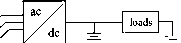
FIGURE 31.20 Dual-vohage architecture based on a dual-wound alternator. the buses and their respective batteries. Control of the bus voltages is achieved via a combination of controlled rectification and field control. Typically, field control is used to regulate one output, while the other output is regulated using a controlled rectifier. Figure 31.21 shows one possible implementation of this architecture. It should be noted that to achieve sufficient output power and power steering from the dual-wound alternator, the winding ratio between the two outputs must be carefully selected. For 42/14 V systems, a winding ratio of 2.5:1 is typical [66]. Advantages of this electrical architecture include low cost. Fiowever, it does not Field Current Regulator 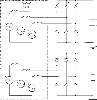 FIGURE 31.19 Dual-vohage architecture based on a dc/dc converter. FIGURE 31.21 Model for a dual-wound alternator system. The two output voltages are regulated through field control and phase control. For a 42/14 V system, a winding ratio between the two stator windings of 2.5:1 is typical. 31.7.3 Dual-Voltage Architectures Conventional automotive electrical systems have a single alternator and battery. Dual-voltage electrical systems have two voltage busses and typically two batteries. Single-battery configurations are possible, but tend to be less cost effective [61]. A variety of different methods for generating and supplying energy to the two busses are under investigation in the automotive community. Many of these have power electronic circuits at their core. This section describes three dual-voltage electrical system architectures that have received broad attention. In all three cases the loads are assumed to be partitioned between the two buses with the starter and many of the other high-power loads on the 42 V bus and most of the lamps and electronics on the 14 V bus. The dc/dc converter-based implementation of Fig. 31.19 is perhaps the most widely considered dual-voltage architecture. In this implementation, an alternator and associated battery provide energy to one bus (typically the 42 V bus), while the other bus is supplied via a dc/dc converter. If a battery is used at the dc/dc converter output, the converter needs to be rated for slightly above average power. Otherwise, the converter needs to be rated a factor of two to three higher to meet peak power requirements [61]. The architecture of Fig. 31.19 has a number of advantages. The dc/dc converter provides high-bandwidth control of energy flow between the two busses, thus enabling better transient control on the 14 V bus than is available in present-day systems or in most other dual-voltage architectures. Furthermore, in systems with batteries on both buses, the dc/dc converter can be used to implement an energy management system so that generated energy is always put to best use. If the converter is bidirectional it can even be used to recharge the high-voltage (starter) battery from the low-voltage battery, thus providing a self-jump-start capability. The major challenge presented by this architecture is the implementation of dc/dc converters having the proper functionality within the tight cost constraints dictated by the automotive industry. Some aspects of design and optimization of converters for this apphcation are addressed in [64]. The dual-stator alternator architecture of Fig. 31.20 is also often considered for dual-voltage automotive electrical systems [65, 66]. In this case, an alternator with two armature windings is used along with two rectifiers to provide energy to  loads loads FIGURE 31.22 alternator. Dual-voltage architecture based on a dual-rectified provide the bidirectional energy control that is possible in the dc/dc converter architecture. Furthermore, there are substantial issues of cross-regulation and transient control with this architecture that remain to be fully explored. In a third architecture, a single-output alternator with a dual-output rectifier is employed. This approach is shown schematically in Fig. 31.22. As with the dual-stator alternator configuration, this architecture has the potential for low cost. One widely considered implementation of the dual-rectified alternator is shown in Fig. 31.23 [65, 67-69]. Despite its simplicity, this implementation approach provides less functionality than the dc/dc converter-based architecture, generates substantial low-frequency ripple which must be filtered, and has serious output power and control limitations [66]. An alternative implementation, proposed in [37] and shown in Fig. 31.24, seems to overcome these limitations, and may potentially provide the same capabilities as the dc/dc converter-based architecture at lower cost. Clearly, this architecture has promise for dual-voltage electrical systems, but remains to be fully explored. Field Cun-ent Regulator field ZX A A FIGURE 31.23 A dual-rectified alternator with a phase-controlled rectifier. Field Cun-ent Regulator field 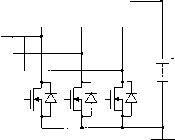 FIGURE 31.24 A dual-rectified alternator with a switched-mode rectifier. 31.8 Electric and Hybrid Electric Vehicles Battery-powered electric vehicles were first introduced over one hundred years ago, and continue to incite great pubhc interest because they do not generate tailpipe emissions. Nevertheless, the low energy storage density and the high cost of suitable batteries makes pure electric vehicles noncompetitive with internal combustion engine vehicles in most applications. An alternative approach that is generating widespread attention is the hybrid electric vehicle (HEV). An HEV combines electrical propulsion with another energy source, such as an internal combustion engine, allowing the traditional range and performance limitations of pure electric vehicles to be overcome [70]. Alternative energy sources, such as fuel cells, are also possible in place of an internal combustion engine. Hybrid electric vehicles can be classified as having either a parallel or series driveline configuration [71]. In a series hybrid electric vehicle all of the propulsion force is produced from electricity; the engine is only used to drive a generator to produce electricity. In a parallel hybrid, propulsive force can come from either the engine or the electrical drive. In both cases, batteries or other electrical storage devices are used to buffer the instantaneous difference between the power needed for propulsion and that generated by the engine. The selection of a series or parallel driveline depends heavily on the performance requirements and mission of the vehicle. In a series hybrid electric vehicle, all power delivered to the wheels of the vehicle must be delivered through the electrical driveline. The electrical driveline components, including the batteries, power electronics, and machine(s), must all be rated 1 ... 78 79 80 81 82 83 84 ... 91 |
|||||||||||||||||||||||||||||||||||||||||||||||||||||||||||||||||||||||||||||||||||||||||||||||||||||||||||||
|
© 2026 AutoElektrix.ru
Частичное копирование материалов разрешено при условии активной ссылки |