 |
 |
 |
| Главная Журналы Популярное Audi - почему их так назвали? Как появилась марка Bmw? Откуда появился Lexus? Достижения и устремления Mercedes-Benz Первые модели Chevrolet Электромобиль Nissan Leaf |
Главная » Журналы » Metal oxide semiconductor 1 ... 79 80 81 82 83 84 85 ... 91 for the peak traction power requirements, making these components relatively large and expensive if performance (e.g. acceleration) comparable to a conventional vehicle is to be achieved. To achieve the required power levels, the electrical drivehne must operate at hundreds of volts, necessitating the electrical subsystem to be sealed from access by the user. The engine, on the other hand, need only be rated to deliver the average power required by the vehicle, which is much lower. In a system that does not require utility recharge of the batteries (i.e. can drive indefinitely on fuel alone), the engine size is set by the power requirements of the vehicle at maximum cruising speed. If utility recharge of the batteries and a battery-limited driving range is acceptable, engine power requirements can be reduced even further. Because the engine does not provide tractive power, it can be designed to run at a single optimized condition, thus maximizing engine efficiency and minimizing emissions. Furthermore, the need for a transmission is eliminated and there is a great deal of flexibility in the engine placement. In a parallel hybrid electric vehicle, traction power is split between the engine and the electrical driveline. One possible approach is to utilize a single machine mounted on the engine crankshaft to provide starting capability along with electrical traction power and regeneration [72-75]. This approach can be replaced or complemented with other approaches, such as use of a power-splitting device such as a planetary gear set [70, 76], or using different propulsion and generation techniques on different sets of wheels [71, 77, 78]. In aU parallel hybrid approaches, some form of transmission is needed to limit the required speed range of the engine. A wide range of divisions between engine size and electrical system size is possible in the paraUel hybrid case, depending on structure. Depending on this split, the necessary electrical driveline system voltage may be as low as 42 V (which is safe for an open wiring system) or as high as 300 V. Also because the electrical subsystem, the internal combustion engine subsystem, or both may provide tractive power under different conditions, there exists a wide range of possible operating approaches for a paraUel hybrid system. Consequently, the control strategy for a parallel hybrid tends to be substantially more complex than for a series hybrid. One parallel hybrid approach that is receiving a lot of attention for near-term vehicles is a light or mild hybrid. In this case, a somewhat conventional vehicle driveline is complemented with a relatively smaU starter/alternator machine mounted on the crankshaft [62, 63, 72-75, 79]. The electrical drive power is typically below lOkW average and 20 kW peak. The starter/alternator can be used to provide rapid, clean restart of the vehicle so that the engine can be turned off at idling conditions and seamlessly restarted. This so-caUed stop and go operation of the engine is valuable for fuel economy and emissions. The starter/alternator can also be used to implement regenerative braking, to provide engine torque smoothing (replacing the flywheel and aUowing differ- ent engine configurations to be used) and to provide boost power for short-term acceleration. At the low-power end, such systems can be integrated directly into the open wiring configuration of a 42 V electrical system, simplifying the vehicle electrical architecture. System level control remains a major chaUenge in realizing the fuU benefits of such systems. Starter/alternator-based hybrids are expected to be a significant near-term application of power electronics and machines in automobUes. 31.9 Summary Power electronics is playing an increasingly important role in the automobUe. It is being used to enhance the output power capability and efficiency of the electrical power generation components. Power electronics is also an enabhng technology for a wide range of new and improved functions that enhance vehicle performance, safety, and functionality. The design of automotive power electronic systems is strongly influenced by the chaUenging electrical and environmental conditions found in the automobile. Important factors include the static and transient voltage ranges, electromagnetic interference and compatibUity requirements, and temperature and other environmental conditions. Some of the most important design considerations for automotive power electronics were addressed in Section 31.3. Section 31.4 described some of the vehicle functions that benefit from, or are enabled by, power electronics. These functions range from hghting to actuation and steering. Power electronic switches also play a central role in multiplexed electrical distribution systems. This role of power electronics was addressed in Section 31.5. The rapid increase in electrical power demand in automobiles is motivating the introduction of new technologies for electrical power generation and control. LundeU alternators are presently used for power generation in automobUes, but are rapidly reaching their power limits. Section 31.6 reviewed the operating characteristics of the LundeU alternator. It also described several techniques for extending the power capabUities of this machine. To meet the growing demand for electrical power, alternative machine and power electronic configurations may be necessary in the future. A number of candidate machine and power circuit configurations were reviewed in Section 31.6. Such configurations can also be applied towards the design of integrated starter/alternators and hybrid propulsion systems, as was discussed in Section 31.8. The increasing electrical and electronic content of automobiles is beginning to stretch the capabUities of the conventional 12 V electrical system. Furthermore, there is a desire on the part of vehicle manufacturers to introduce new high-power loads, such as electromechanical engine valves, active suspension, and integrated starter/alternator. These are not likely to be practical within the present 12 V framework. These challenges are forcing the automotive industry to seriously consider high and dual voltage electrical systems. The ongoing developments in this area were reviewed in Section 31.7 The increasing electrical content of vehicles both underscores the need for power electronics and reflects the benefits of their introduction. It is safe to say that power electronics will continue to play an important role in the evolution of automobiles far into the future. References 1. Automotive Electric/Electronic Systems, 2nd ed (1995) Robert Bosch GmbH, Stuttgart, Germany, 1995. 2. T. Denton (1995) Automotive Electrical and Electronic Systems, Arnold, London, UK. 3. SAE Electronic Systems Committee (1978) Recommended environment practices for electronic equipment design, SAE Recommended Practice SAE J1211, November, Society of Automotive Engineers, Warrendale, PA, USA. 4. SAE Handbook (1999) Society of Automotive Engineers, Warrendale, PA, USA. 5. J. Alkalay et al (1989) Survey of conducted transients in the electrical system of a passenger automobile, IEEE Symposium on Electromagnetic Compatibility, IEEE, New York, pp. 271-278. 6. SAE EMI Standards Committee (1995) Immunity to conducted transients on power leads, SAE Standard SAE Jl 113/11, June, Society of Automotive Engineers, Warrendale, PA, USA. 7. J. G. Kassakian, M. R Schlecht, and G. C. Verghese (1991) Principles of Power Electronics, Addison-Wesley, New York. 8. V. Cahskan, D. J. Perreauh, T. M. Jahns and J. G. Kassakian (1999) Analysis of three-phase rectifiers with constant-voltage loads, IEEE Power Electronics Specialists Conference, Charleston, SC, USA, June, IEEE, New York, pp. 715-720. 9. SAE EMI Standards Committee (1995) Limits and methods of measurement of radio disturbance characteristics of components and modules for the protection of receivers used on board vehicles, SAE Standard SAE J1113/41, July, Society of Automotive Engineers, Warrendale, PA, USA. 10. SAE EMI Test Methods and Standards Committee (1994) Electromagnetic compatibility-component test procedure - Part 42 - conducted transient emissions, SAE Standard SAE J1113/42, July, Society of Automotive Engineers, Warrendale, PA, USA. 11. T. K. Phelps and W. S. Tate (1979) Optimizing passive input fiher design. Proceedings of International Conference on Power System Technology, POWERCON 6, May, 1979, Power Concepts, Inc., Oxnard, California, pp. Gl-l-Gl-19. 12. M. J. Nave (1991) Power Line Filter Design for Switched-Mode Power Supplies, Van Nostrand Reinhold, New York. 13. R. D. Middlebrook (1976) Input filter considerations in design and application of switching regulators, IEEE Industry Applications Society Annual Meeting, 1976, IEEE, New York. 14. H. W. Ott (1988) Noise Reduction Techniques in Electronic Systems, John Wiley, New York. 15. Automotive Handbook, 3rd ed. (1993) Robert Bosch GmbH, Stuttgart, Germany. 16. R. K. Jurgen ed. (1999) Automotive Electronic Handbook, 2nd ed., McGraw HiU, New York. 17. R S. Schwartz, W. Hendrischk and J. Jiao (1996) Intelligent automotive lighting. Proceedings of International Congress on Transportation Electronics 1994 pp. 299-303, Society of Automotive Engineers, Warrendale, PA, USA. 18. T. Yamamoto and T. Futami (1990) Development of 2-lamp type HID headlighting system. Proceedings of the SAE International Congress and Exposition pp. 1-6 Detroit, MI, USA, February, 1990 SAE paper 900562, Society of Automotive Engineers, Warrendale, PA, USA. 19. B. Woerner and R. Neumann (1996) Motor vehicle lighting systems with high intensity discharge lamps. Proceedings of the SAE International Congress and Exposition, Detroit, MI, USA, February, 1990 SAE paper 900569, Society of Automotive Engineers, Warrendale, PA, USA. 20. L. So, R Miller, and M. OHara (2001) 42V-PWM - lighting the way in the new millennium, Fugure Transportation Technology Conference, Costa Mesa, CA, USA, 2000 SAE paper 2000-01-3053, Society of Automotive Engineers, Warrendale, PA, USA. 21. H. P. Schoner (1992) Piezo-electric motors and their apphcations, Ferroelectrics 133, 27-34. 22. J. Wallaschek (1985) Piezoelectric ultrasonic motors. Journal of Intelligent Material Systems and Structures 6, 71-83. 23. T. Sashida and T. Kenjo (1993) An Introduction to Ultrasonic Motors, Oxford University Press, New York. 24. T. Sashida (1982) Japanese Patent no. 58-148682, February. 25. M. A. Theobald, B. Lesquesne, and R. Henry (1994) Control of engine load via electromagnetic valve actuators. International Congress and Exposition Detroit, MI, USA, February, 1994, SAE Paper 920447, Society of Automotive Engineers, Warrendale, PA, USA. 26. J. L. Oldenkamp and D. M. Erdman (1989) Automotive electrically driven air conditioner system. Proceedings of the IEEE Workshop on Automotive Power Electronics, IEEE, New York, pp. 71-72. 27. J. R. Valentine (1996) Electric steering power electronics, IEEE Workshop on Power Electronics in Transportation, Dearborn MI, USA, October, 1996, IEEE, New York, pp. 105-110. 28. J. F. Ziomek (1973) One-Wire automotive electrical systems Proceedings of the SAE International Automotive Engineering Congress, Detroit, MI, USA, January, 1973, SAE Paper 730132, Society of Automotive Engineers, Warrendale, PA, USA. 29. M. Leonard (1991) Multiplexed buses unravel auto wiring. Electronic Design August 8, 83-90. 30. Class В Data Communication Network Interface (1992) SAE J1850, Rev. Aug 91, Society of Automotive Engineers, Warrendale, PA, USA. 31. CAN Specification (1991) Robert Bosch GmbH, Stuttgart, Germany. 32. R. Frank (1985) Replacing relays with semiconductor devices in automotive apphcations, SAE Paper 880177, Society of Automotive Engineers, Warrendale, PA, USA, pp. 47-53. 33. A. Marshall and K. G. Buss (1990) Automotive semiconductor switch technologies. Proceedings of IEEE Workshop on Electronic Applications in Transportation, Dearborn, MI, USA, October, 1990, Society of Automotive Engineers, Warrendale, PA, USA, pp. 68-72. 34. F. Krieg (1993) Automotive relays. Automotive Engineering, March 21-23. 35. K. Furuichi, K. Ishida, K. Enomoto and K. Akashi (1992) An implementation of class A multiplex application SAE International Congress and Exposition, Multiplex Technology Applicatioins to Vehicle Wire Harnesses, Detroit, MI, USA, February, 1992 pp. 125-133 SAE Paper 920230, Society of Automotive Engineers, Warrendale, PA, USA. 36. S. Kuppers and G. Henneberger (1997) Numerical procedures for the calculation and design of automotive alternators, IEEE Transactions on Magnetics 33(2), 2022-2025. 37. D. Perreault and V. CaHskan (2000) A new design for automotive alternators lEEE-SAE International Conference on Transportation Electronics (Convergence), Dearborn, MI, USA, October, 2000, SAE Paper 2000-01-C084, Society of Automotive Engineers, Warrendale, PA, USA. 38. G. Henneberger and S. Kuppers (1994) Improvement of the output performance of claw-pole alternators by additional permanent magnets, Proceedings of the International Conference on Electrical Machines, Istanbul, Turkey vol. 2, pp. 472-476 (1998). 39. J. M. Miller, D. Goel, D. Kaminski, H.-P. Shoener and T. M. Jahns (1998) Making the case for a next generation automotive electrical system, International Congress on Transportation Electronics (Convergence), Dearborn, MI, USA, October, 1998, Society of Automotive Engineers, Warrendale, PA, USA, pp. 41-5. 40. T. A. Radomski (1989) Alternating current generator, US Patent, No. 4,882,515, November 21. 41. T. M. Jahns and V. Caliskan (1999) Uncontrolled generator operation of interior PM synchronous machines following high-speed inverter shutdown, IEEE Transactions on Industry Applications 35(6), 1347-1357. 42. G. Venkataramanan, B. Milovska, V. Gerez and H. Nehrir (1996) variable speed operation of permanent magent alternator wind turbines using a single switch power converter, Journal of Solar Energy Engineering-Transactions of the ASME 118(4), 235-238. 43. W. T. Balogh (1998) Boost converter regulated ahernator, US Patent No. 5,793,625, August 11. 44. H.-J. Gutt and J. MuUer (1994) New aspects for developing and optimising modern motorcar generators, IEEE Industry Applications Society Annual Meeting Denver, CO, USA, October, 1994, IEEE, New York. 45. M. Naidu, N. Boules and R. Henry (1995), A high-efficiency, high power generation system for automobiles, Proceedings of the IEEE Industry Applications Society, IEEE, New York, pp. 709-716. 46. C. D. Syverson and W. R Curtiss (1996) Hybrid alternator with voltage regulator, US Patent No. 5,502,368, March 26. 47. Z. Zhang, R Profumo and A. Tenconi (1994) Wheels axial flux machines for electric vehicle applications, Proceedings of the International Conference on Electrical Machines, vol. 2, pp. 7-12. 48. L. Givens (1990) A technical history of the automobile, Automotive Engineering, 61-67. 49. S. M. Terry (1954) 12 volts presents its case, SAE Journal, 29-30. 50. H. L. Hartzell (1954) Its Still 12 Volts!, SAE Journal, 63. 51. J. G. W. West (1989) Powering Up - a higher system voltage for cars, lEE Review, 29-32. 52. J. M. Miller (1986) Multiple voltage electrical power distribution system for automotive applications, Intersociety Energy Conversion Engineering Conference, Washington, DC, USA, August, 1996, IEEE, New York. 53. J. G. Kassakian, H. C. Wolf, J. M. Miller and C. J. Hurton (1996) Automotive electrical systems circa 2005, IEEE Spectrum, August 22-27. 54. J. V. Hellmann and R. J. Sandel (1992) Dual/high vohage electrical systems, Euture Transportation Technology Conference and Exhibition, August, 1991, SAE 911652, Society of Automotive Engineers, Warrendale, PA, USA. 55. SAE J2232 (1992) Vehicle system vohage - initial recommendations, SAE Information Report J2232, June. 56. Draft specification of a dual voltage vehicle electrical power system 42V/14/V (1997) Eorum Bordnetz, Working Document, Germany, March 4. 57. Heated Windshield, PPG Industries Inc., Pittsburg, PA, USA. 58. Automotive industry association expects production of fuel-efficient cars to begin by 2000 The Week in Germany, German Information Center, New York, NY, USA, September 15, p. 4. 59. Review of the Research Program of the Partnership for a New Generation of Vehicles, (1996) Second Report, National Academy Press, Washington, DC, USA. 60. MIT prof drives the shift to 42-V Cars (1999) Electronic Engineering Times, (1053), 115-116, March 22. 61. K. K. Afridi (1998) A Methodology for the Design and Evaluation of Advanced Automotive Electrical Power Systems, PhD Thesis, Department of Electrical Engineering and Computer Science, Massachusetts Institute of Technology, Cambridge, MA, USA, February. 62. J. M. Miller, K. Hampton, and R. Eriksson (2000) Identification of the optimum vehicle class for the application of 42V integrated Starter generator lEEE-SAE International Conference on Transportation Electronics (Convergence), Dearborn, MI, October 2000, SAE Paper 2000-01-C073, Society of Automotive Engineers, Warrendale, PA, USA. 63. E. C. Lovelace, T. M. Jahns, and J. H. Lang (2000) Impact of saturation and inverter cost on interior PM synchronous machine drive optimisation, IEEE Transactions IAS 36(3), 2000. 64. T. C. Neugebauer and D. J. Perreault (2000) Computer-aided optimisation of dc/dc converters for automotive applications, IEEE Power Electronics Specialist Conference, Galway, Ireland, June, 2000, IEEE, New York, pp. 689-695. 65. J. C. Byrum (2000) Comparative Evaluation of Dual-Voltage Automotive Alternators, SM Thesis, Department of Electrical Engineering and Computer Science, Massachusetts Institute of Technology, Cambridge, MA, USA, September. 66. V. Cahskan (2000) A Dual/High-Voltage Automotive Electrical Power System with Superior Transient Performance, PhD Thesis, Department of Electrical Engineering and Computer Science, Massachusetts Institute of Technology, Cambridge, MA, USA, September. 67. C. R. Smith, (1991) Review of heavy duty voltage systems, International Off-Highway & Powerplant Congress and Exposition, September, 1991, SAE Paper 911857, Society of Automotive Engineers, Warrendale, PA, USA. 68. J. Becker, M. Pourkermani, and E. Sarare (1992) Dual-vohage Aher-nators, International Truck and Bus Meeting and Exposition, Toledo, OH, USA, November, 1992, SAE Paper 922488, Society of Automotive Engineers, Warrendale, PA, USA. 69. J. ODwyer, C. Patterson, and T. Reibe (1996) Dual vohage ahernator, lEE Colloquium on Machines for Automotile Applications, London, UK, November, 1996, lEE, UK, pp. 4/1-4/5. 70. D. Hermance and S. Sasaki (1995) Hybrid electric vehicles take to the streets, IEEE Spectrum, November, pp. 48-52. 71. A. F. Burke (1992) Hybrid/electric vehicle design options and evaluations, Electric and Hybrid Vehicle Technology (SP-915) International Congress and Exposition, Detroit, MI, USA, February, 1992, SAE Paper 920447, Society of Automotive Engineers, Warrendale, PA, USA. 72. K. Nakano and S. Ochiai (2000) Development of the motor assist system for the hybrid automobile - the insight, lEEE-SAE International Conference on Transportation Electronics (Convergence), Dearborn, MI, USA, October, 2000, SAE Paper 2000-01-C079, Society of Automotive Engineers, Warrendale, PA, USA. 73. R. L. Davis, T. L. Kizer (2000) Energy management in Daimler-Chryslers PNGV concept vehicle, lEEE-SAE International Conference on Transportation Electronics (Convergence), Dearborn, MI, USA, October 2000, SAE Paper 2000-01-C063, Society of Automotive Engineers, Warrendale, PA, USA. 74. A. Gale and D. Brigham (2000) Starter/alternator design for optimised hybrid fuel economy, lEEE-SAE International Conference on Transportation Electronics (Convergence), Dearborn, MI, USA, October 2000, SAE Paper 2000-01-C06, Society of Automotive Engineers, Warrendale, PA, USA. 75. J. M. MiUer, A. R. Gale, and V. A. Sankaran (1992) Electric drive subsystem for a low-storage requirement hybrid electric vehicle, IEEE Transaction on Vehicular Technology 48(6). 76. S. Abe (2000) Development of the hybrid vehicle and its future expectation, lEEE-SAE International Conference on Transportation Electronics (Convergence), Dearborn, MI, USA, October, 2000, SAE Paper 2000-01-C042, Society of Automotive Engineers, Warrendale, PA, USA. 77. W. L. Shepard, G. M. Claypole, M. G. Kosowski, and R. E. York (2000) Architecture for robust efficiency: GMs precept PNGV vehicle. Future Car Congress, Arlington, VA, USA, April, 2000, SAE Paper 2000-01-1582, Society of Automotive Engineers, Warrendale, PA, USA. 78. M. G. Kosowski and R H. Desai (2000) A parallel hybrid traction system for GMs Precept PNGV vehicle. Future Car Congress, Arlington, VA, USA, April, 2000, SAE Paper 2000-01-1534, Society of Automotive Engineers, Warrendale, PA, USA. 79. J. M. MiUer, A. R. Gale, R J. McCleer, R Lonardi, and J. H. Lang (1998) Starter alternator for hybrid electric vehicle: comparison of induction and variable reluctance machines and drives, IEEE IAS Annual Meeting, St Louis, MO, USA, October, 1998, IEEE, New York. Power Quality S. Mark Halpin, Ph.D. Angela Card Department of Electrical and Computer Engineering Mississippi State University, Mississippi State, Mississippi 39762, USA 32.1 Introduction...................................................................................... 817 32.2 Power Quality.................................................................................... 818 32.2.1 Steady-State Voltage Frequency And Magnitude 32.2.2 Voltage Sags 32.2.3 Grounding 32.2.4 Harmonics 32.2.5 Voltage Fluctuations and Flicker 32.2.6 Transients 32.2.7 Monitoring and Measurement 32.3 Reactive power and harmonic compensation........................................... 823 32.3.1 Typical Harmonics Produced by Equipment 32.3.2 Resonance 32.3.3 Harmonic Filters 32.4 IEEE Standards................................................................................... 827 32.5 Conclusions....................................................................................... 828 References......................................................................................... 828 32.1 Introduction Power electronics and power quality are irrevocably linked together as we strive to advance both broad areas. With the dramatic increases over the last 20 years in energy conversion systems utilizing power electronic devices, we have seen the emergence of power quality as a major field of power engineering. Simply put, power electronic technology has played a major role in creating power quality, and simple control algorithm modifications to this same technology can often play an equally dominant role in enhancing overaU quality of electrical energy avaUable to end-users. Power electronics has given us, as an industrial society, a plethora of new ways to manufacture products, provide services, and utUize energy. From a power quality impact viewpoint, applications such as 1. switched-mode power supplies, 2. dc arc furnaces, 3. electronic fluorescent lamp ballasts, 4. adjustable speed drives, and 5. flexible ac transmission components are often cause for concern. From a utUity supply system viewpoint, these converter-based systems can lead to operational and life expectancy problems for other equipment, possibly not owned or operated by the same party. It was from this initial perspective that the field of power quality emerged. In most cases, the same devices and systems that create power quality problems can also be used to solve power quality problems. Problem solving applications such as 1. active harmonic filters, 2. static and adaptive var compensators, and 3. uninterruptable power supplies aU utilize the same switching device technology as the problem causing applications. As the number of potentially problematic power electronic based loads has increased over time, so has attention given to enhanced converter control to maximize power quality. Perfect examples of these improvements include: 1. unity power factor converters, 2. dip-proof inverters, and 3. limited-distortion electronic lamp baUasts. WhUe these direct product enhancements are not mandatory in North America, todays global economy necessitates consideration of power quality standards and limits in order to conduct business in the European Union. While many studies suggest increases in power electronic-based energy UtUization as high as 70-80% (of aU energy consumed), it is equally clear that we are beginning to realize the total benefit of such end-use technologies. Power quality problems associated with grounding, sags, harmonics, and transients wiU continue to increase because of the sheer number of sensitive electronic loads expected to be placed in service. At the same time, we are only now beginning to realize the total benefits that such loads can offer. 32.2 Power Quality The term power quality means different things to different people. To utility suppliers, power quality initially referred to the quality of the service delivered as measured by the consumers ability to use the energy delivered in the desired manner. This conceptual definition included such conventional utility planning topics as voltage and frequency regulation and rehability. The end-users definition of power quality also centers around their ability to use the delivered energy in the desired manner, but the topics considered can be much more specific and include magnitude and duration of different events as well as waveshape concerns. Fortunately, a good working definition of power quality has not been a point of contention, and most parties involved consider quality power to be that which allows the user to meet their end-use goals. The working definition is not complicated by particular issues; engineers are well aware that topics from many aspects of power engineering may be important. Power quality can be roughly broken into categories as follows: 1. steady-state voltage magnitude and frequency, 2. voltage sags, 3. grounding, 4. harmonics, 5. voltage fluctuations and flicker, 6. transients, and 7. monitoring and measurement. The remainder of this section discusses each of the major categories in turn. 32.2.1 Steady-State Voltage Frequency And Magnitude In most areas of North America, steady-state frequency regulation is not a significant issue due to the sufficient levels of generating capacity and the strong interconnections among generating companies and control areas. In other parts of the world, and North America under extreme conditions, frequency can deviate to Hz during periods of insufficient generating capacity. Under transient conditions, frequency can deviate up to 1-2 Hz. Frequency deviations can affect power electronic equipment that use controlled switching devices unless the control signals are derived from a signal that is phase-locked with the applied voltage. In most cases, phase locks are used, or the converters consist of uncontrolled rectifiers. In either case, frequency deviations are not a major cause of problems. In most cases, frequency deviations have more impacts on conventional TABLE 32.1 ANSI C84.1 voltage ranges. Range A is for normal conditions, Range В is for emergency or short-time conditions
equipment that does not use electronics or in very inexpensive electronic devices. Clocks can run fast (or slow), motor speeds can drop (or rise) by a few revolutions per minute, etc. In most cases, these effects have minimal economic impact and are not considered a real power quality problem. Steady-state voltage regulation is a much more pronounced issue that can impact a wide range of end-use equipment. In most cases, utility supply companies do a very effective job of providing carefully regulated voltage within permissible ranges. In North America, ANSI Standard C84.1 suggests steady-state voltage ranges both at the utility service entrance and at the point of connection of end-use equipment. Furthermore, equipment manufacturers typically offer equipment that is tolerant of steady-state voltage deviations in the range of ±10%. Table 32.1 shows the voltage ranges suggested by ANSI C84.1, with specific mention of normal (Range A) and contingency (Range B) allowable voltages, expressed in percent. Virtually all equipment, especially sensitive electronic equipment, can be affected by voltages deviating outside the ±10% range. In most cases, overvoltages above ±10% lead to loss of life, usually over time; excessive overvoltages can immediately fail equipment. Undervoltages below -10% usually lead to excessive current demands, especially for equipment that has a controlled output like an adjustable speed drive controlling a motor to a constant speed/torque point. The impacts of these prolonged excessive currents can be greater voltage drop, temperature rise in conductors, etc. In the extreme, undervoltages of greater than 15-20% can cause equipment to immediately trip. In most cases, such extreme undervoltages are associated with system faults and the associated protection system. These extreme undervoltages are so important that they are classified in a power quality category of their own, called voltage sags. 32.2.2 Voltage Sags Other than improper grounding, voltage sags are probably the most problematic of all power quality problems. At this time, a number of standards-making bodies, including IEEE, ANSI, and lEC, are working on standards related to sags. In most cases, sags are generally agreed to be more severe and outside of the scope of ANSI C84.1 and they are temporary in nature due to the operation of system protection elements. Because the electrical system is a continuous electrical circuit, faults in any location will have some impact on voltages throughout the Fused Tap #1 -► Feeder #1 Utility Substation equivalent transformer Feeder #2 Fused Tap #2 FIGURE 32.1 Overhead distribution system. network. Of course, areas closer to the faulted area wiU see a greater voltage sag due to the fault than other, more (electrically) remote areas. Sags can originate anywhere in a system, but are more pronounced in utility distribution systems because of the greater exposure of low-voltage systems to the causes of short circuits. Most utility companies implement distribution system protection in what is known as a fuse saving methodology. Figure 32.1 shows a typical overhead distribution system with two feeders being supplied from the same substation transformer. Each primary circuit has its own automatic circuit recloser (ACR) and shows one fused tap. With the protection system set up based on fuse-saving methodology, any fault downstream of a fault wiU be cleared first by the substation recloser foUowed by a reclosing operation (re-energization of the circuit) to 2 seconds later. If the fault is StiU present, the closest fuse should blow to permanently isolate the fault. (Note that in some cases, multiple reclosing attempts are made prior to the clearing of the fuse.) For a fault on the load side of Fused Tap #2 in Figure 32.1, customers on Feeder 1 wiU see a voltage sag determined by the system and transformer impedance at the substation. Because this impedance is typically in the same order (or larger) as the feeder circuit impedance, a sag in substation bus voltage of 50% is common. This sag wiU persist until Feeder 2 is cleared by the recloser opening. When the recloser reenergizes the circuit, a permanent fault wiU stiU be present and the substation bus wiU again experience a voltage sag. Of course, any sag in substation bus voltage wiU be delivered directly to aU customers on Feeder #1, even though there is no electrical problem on that feeder. Figure 32.2 shows a possible rms voltage profile that might be supplied to the customers on Feeder 1 for a permanent fault on the load side of Fused Tap #2. Only one recloser operation is shown prior to fuse clearing. Just based on the voltage information shown in Figure 32.2, it is impossible to teU if the end-use loads on Feeder #1 wiU experience a problem. Equipment tolerance curves are required to assess the vulnerabUity of equipment to voltage deviations, including sags, and aU equipment is different. Figure 32.3 shows the lower portions of two equipment ё о > Ti e (s) FIGURE 32.2 RMS vohage supphed to Feeder #1 customers. tolerance curves, the (older) CBEMA and the (newer) ITIC curves for computer equipment. Most, but not aU, power electronic based equipment has a simUar shape. Voltage sags with a duration that correspond to a point that is below and to the right of the tolerance curve wiU result in loss of equipment function, whUe sags of duration that plot above and to the left of the tolerance curve wiU not affect equipment performance. Note that only the lower portion of the curve has been shown; an upper tolerance curve also exists that is often used in transient (overvoltage) studies. Voltage sags are probably the most common power quality problem that is given to the end-user by the supplying UtUity. Fiowever, improper equipment grounding is responsible for the vast majority of power quality problems on the customers side of the meter. о Duration of Sag (illiseconds) [0 to 6,000 Cycles] FIGURE 32.3 CBEMA (curved line) and ITIC (square shape) tolerance curves. 32.2.3 Grounding Grounding of equipment was originally conceived as a personnel safety issue. However, the presence of an electrical conductor that is at zero potential has been widely used in many power electronic and microprocessor-controlled loads. In the United States, electrical systems in residential, commercial, and industrial facilities fall under the purview of the National Electric Code which establishes specific criteria for grounding of equipment. While it was once thought that proper grounding according to the NEC was detrimental to power quality concerns, these opinions have gradually faded over time. From a power quality perspective, improper grounding can be considered in three broad categories: 1. ground loops, 2. improper neutral-to-ground connections, and 3. excessive neutral-to-ground vohage. The ground loop problem is a significant issue when power, communications, and control signals all originate in different locations, but come together at a common electrical point. Transients induced in one location can travel through the created ground loop, damaging equipment along the way. Improper neutral-to-ground connections will create a noisy ground reference that may interfere with low-voltage communications and control devices. Excessive neutral-to-ground voltage may damage equipment that is not properly insulated or that has an inexpensive power supply. Figure 32.4 shows a common wye-connected service (assumed at the terminals of a transformer) that supplies power to equipment that also is remotely monitored and controlled from another location with a separate ground reference. For any shift in ground potential for the power circuit, often caused by hghtning as shown in Figure 32.4, potentially large currents can flow through the grounding circuits and through the sensitive electronic equipment. Such currents can easily Load Equipment О В FIGURE 32.5 Improper neutral-to-ground connections. lead to equipment damage. Situations like these are common in 1. residential areas, if power and CATV or telephone grounds are not the same, and 2. commercial and industrial complexes consisting of multiple buildings with hnking communications, computer, or control circuits, when each building has its own power service (and therefore ground). Figure 32.5 shows an example of an improper neutral-to-ground connection, and how this connection can create power quality problems. Load current returning in the neutral conductor will, at the point of improper connection to ground, divide between neutral and ground. This current flow in the ground conductor will produce a voltage at the load equipment, which can easily disrupt equipment operation. Figure 32.6 shows an example of the possibility for excessive neutral-to-ground voltage and how this can lead to power quality problems.  p о w Load Equipment С О N Т R О L P О Load Equipment В FIGURE 32.4 Powering and control ground loop. FIGURE 32.6 Excessive neutral-to-ground voltage. For load equipment that produces significant voltage drop in the neutral, such as laser printers and copying machines when the thermal heating elements are on, the voltage fi-om the neutral to the ground reference inside the equipment can exceed several volts. In many cases, this voltage is sufficient to damage printed circuit boards, disrupt control logic, and fail components. 32.2.4 Harmonics In most cases, power electronic equipment is considered to be the cause of harmonics. While switching converters of aU types produce harmonics because of the nonlinear relationship between the voltage and current across the switching device, harmonics are also produced by a large variety of conventional equipment including: 1. power generation equipment (slot harmonics), 2. induction motors (saturated magnetics), 3. transformers (overexcitation leading to saturation), 4. magnetic-baUast fluorescent lamps (arcing), and 5. ac electric arc furnaces (arcing). AU these devices wiU cause harmonic currents to flow, and some devices actually directly produce voltage harmonics. Any ac current flow through any circuit at any frequency wiU produce a voltage drop at that same frequency. Fiarmonic currents, which are produced by power electronic loads, wiU produce voltage drops in the power supply impedance at those same harmonic frequencies. Because of this interrelationship between current flow and voltage drop, harmonic currents created at any location wiU distort the voltage in the entire supply circuit. In most cases, equipment is not overly sensitive to the direct impacts of harmonic current flow. Note, however, that equipment heating is a function of the rms value of the current, which can significantly exceed the fundamental frequency value when large harmonic components are present. It is because harmonic currents produce harmonic voltages that there is a real power quality concern. Most equipment can operate satisfactorily as long as the voltage distortion at the equipment terminals does not exceed around 5%. Exceptions to this general rule include ripple-control systems for converters (which are impacted by smaU even-order harmonics) and smaU harmonics at sufficiently high frequency to produce multiple zero crossing in a waveform. (Note that voltage notching due to simultaneous commutation of switching devices can also create multiple zero crossings.) Such a muhiple crossing scenario is shown in Figure 32.7 and represents a 60 Fiz waveform plus a 1% voltage harmonic at 3,000 Fiz. Converters that have a time-limited firing signal can directly suffer from excessive voltage distortion. For a six-pulse converter, a maximum time of 1/(6 x 60) seconds is avaUable to turn on a switching device. SimUarly, for a twelve-pulse converter, a 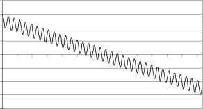 Tie(s) FIGURE 32.7 Muhiple zero crossings. maximum of 1/(12 x 60) is available to turn on a switching device. Considering that aU switching devices have a short (but nonzero) turn-on time, manufacturers tend to design drive circuits that bring up the firing pulse for a limited amount of time. If, for example, a firing pulse is maintained for 100 is, the device must begin conduction in that time. In situations where voltage distortion is excessive, the device to be switched could be reverse biased during the first several miUiseconds of the time avaUable for device firing during which time conduction cannot begin. If the firing signal is removed before the certain classes of switching devices are correctly biased, conduction wiU not begin at aU. This situation, commonly caUed a misfire, can lead to equipment misoperation and faUure. Because some switching devices can conduct in both directions when the firing signal is applied (but only one direction is intended to carry appreciable current), applying the firing pulse at a time when the voltage is of the wrong polarity can destroy the device. Excessive voltage distortion can certainly lead to such a situation, and manufacturers typically design products to function only under hmited-distortion conditions. Because of the numerous potential problems with harmonic currents, standards exist for their control. The lEC goes as far as to limit the harmonic currents produced by certain individual pieces of equipment, while the IEEE takes a more system-level point of view and prescribes limits for harmonic currents for a facility as a whole, including one or more harmonic producing loads. Fiarmonic standards wiU be further discussed in Section 32.4. 32.2.5 Voltage Fluctuations and Flicker Voltage flicker is not directly caused by electronic loads except in the largest of apphcations. Voltage fluctuations, and the corresponding light flicker due to them, are usually created by large power fluctuations at frequencies less than about 30 Fiz. In most applications, only 1. large dc arc furnaces and welders. 2. reactive power compensators, and 3. cycloconverters are potentially problematic. Each of these types of end-use devices can create large, low-frequency (about 30 Hz or less) variations in the system voltage, and can therefore lead to voltage flicker complaints. At this time, the IEEE prescribes a flicker curve based originally on research conducted by General Electric. The lEC, however, has adopted a different methodology that can consider voltage fluctuations and flicker that are more complex than those considered by the IEEE flicker curve. Most equipment is not sensitive to the voltage fluctuations that cause flicker complaints. The change in output of incandescent lamps as viewed by human observers becomes objectionable at levels of change around 0.3%, but electronic equipment will not be affected at all. Because most utility supply companies limit voltage fluctuations, regardless of the frequency of repetition, to less than a few percent, equipment malfunction or damage due to flicker is very rare. Figures 32.8 and 32.9 show plots of single-cycle rms voltage fluctuations due to large dc welders and arc furnaces, respectively; it is clear that the magnitude of the fluctuations are well above the level that could impact equipment. The waveform in Figure 32.8 probably would generate numerous light flicker complaints, whereas the waveform in Figure 32.9 probably would not. Neither would disrupt equipment. Because of the advances in power electronics that have offered devices with higher power ratings, reactive compensation systems have been developed to compensate for voltage fluctuations by adding or removing reactive power from the supply circuit. These devices have allowed large flicker-producing loads like arc furnaces to be served from utility circuits that, without the compensator, could not serve the load. However, because the compensators can so directly impact system voltage, they can create flicker problems if they are not properly applied and controlled. 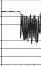 Ti e (s) FIGURE 32.8 Single-cycle rms voltage fluctuations due to a large dc welder. lIlLi. О > BBBIilKilME Ti e (s) FIGURE 32.9 Single-cycle rms voltage fluctuations due to a large dc arc furnace. 32.2.6 Transients Transients, especially in the voltage supply, can create numerous power quality problems. The major sources of transients are 1. lightning, 2. utility circuit switching and fault clearing, 3. capacitor switching, and 4. load switching. Lightning events can create the most severe overvoltages, but these transients decay rapidly. A typical lightning transient has decayed to zero in a few hundred microseconds, but it can reach a peak magnitude of several hundred percent if not controlled with surge suppression devices. Other categories of transients associated with power system switching are much smaller in magnitude (typically less than 200%), but at least in the order of several hundred milliseconds. Considering the energy available in a transient, therefore, there is considerable overlap in the range of severity of lightning and switching transients. It is the available energy that typically determines whether or not equipment will be affected or damaged. Figure 32.10 shows a capacitor switching transient on a low-voltage (480 V) circuit. The magnitude and duration of the event are quite clear. Transients such as those shown in Figure 32.10 are generally sufficient to cause nuisance trips of electronic loads like adjustable speed drives. For these types of loads, the protection system settings are usually very tight due to the use of sensitive switching devices. Overcurrent and overvoltage settings of 120% are not uncommon. For a transient similar to that shown in Figure 32.10, there is sufficient overvoltage for very large currents to flow through any conducting switching device to the drives dc bus. The devices protection system see these overcurrents as a fault, and trip the drive. Similarly, the overvoltage at the terminals can be passed through to the dc bus and accumulate, where the drive may trip due to overvoltage on the dc bus. 1 ... 79 80 81 82 83 84 85 ... 91 |
|
© 2026 AutoElektrix.ru
Частичное копирование материалов разрешено при условии активной ссылки |